

 русский
 Español
 عربى
عربى-
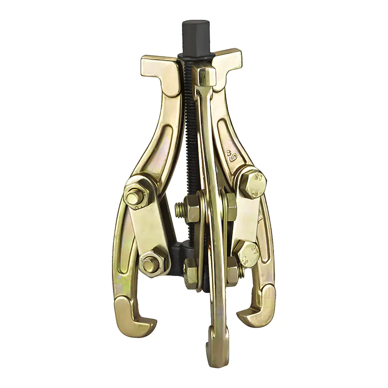
Model: SN0101
-
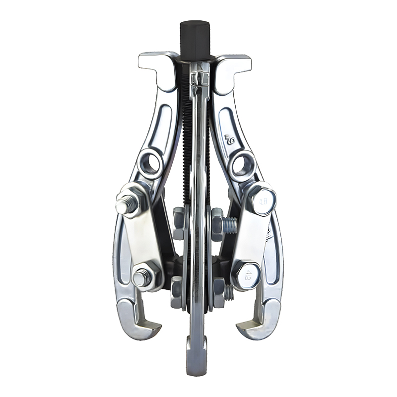
Model: SN0102-1
-
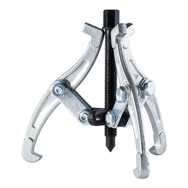
Model: SN0103
-
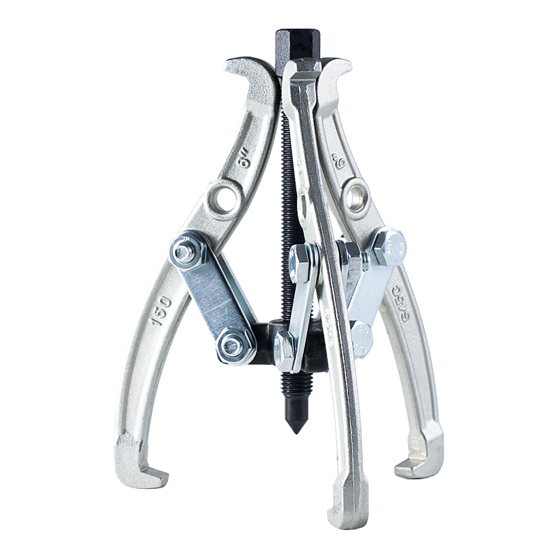
Model: SN0102 SN0107
-
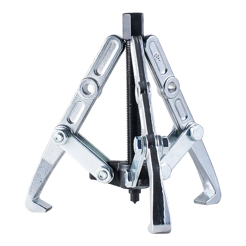
Model: SN0108 SN0109
-
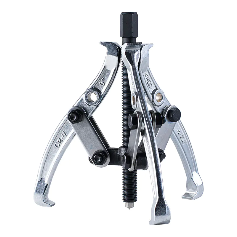
Model: SN0105
-
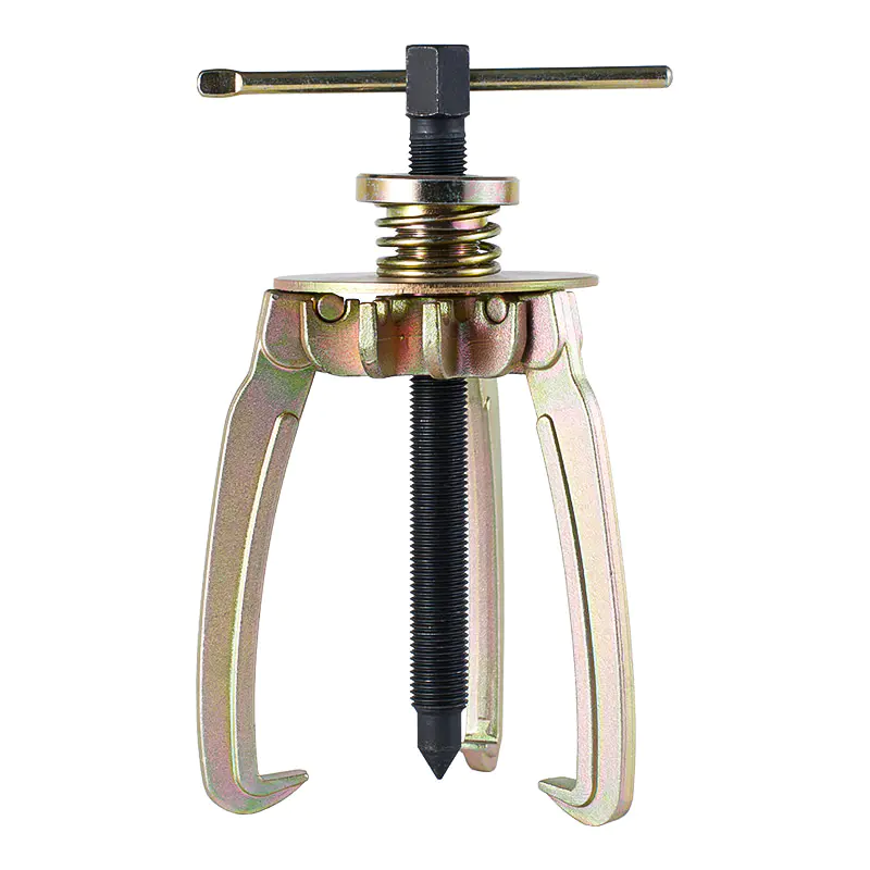
Model: SN0106
-
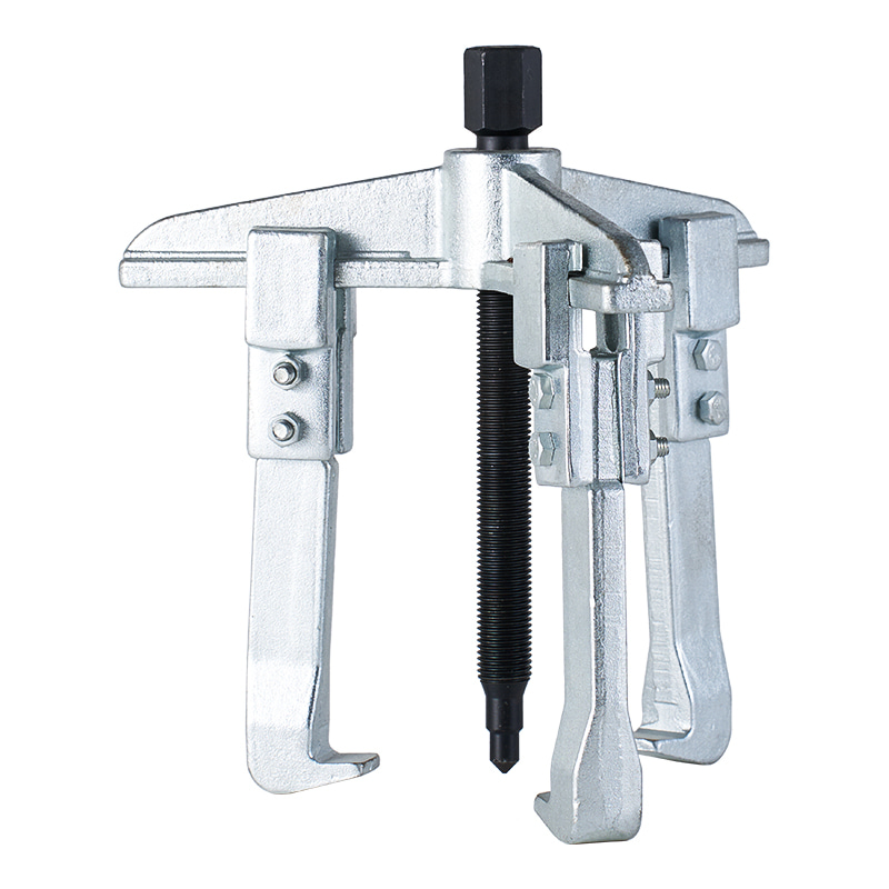
Model: SN0110
-
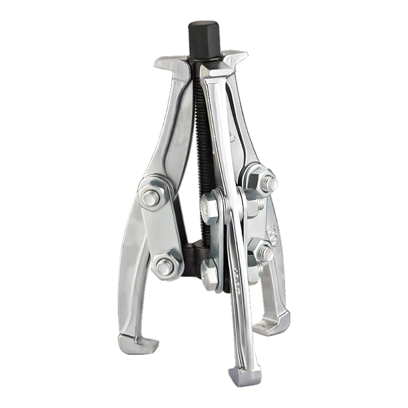
Model: SN0118
-
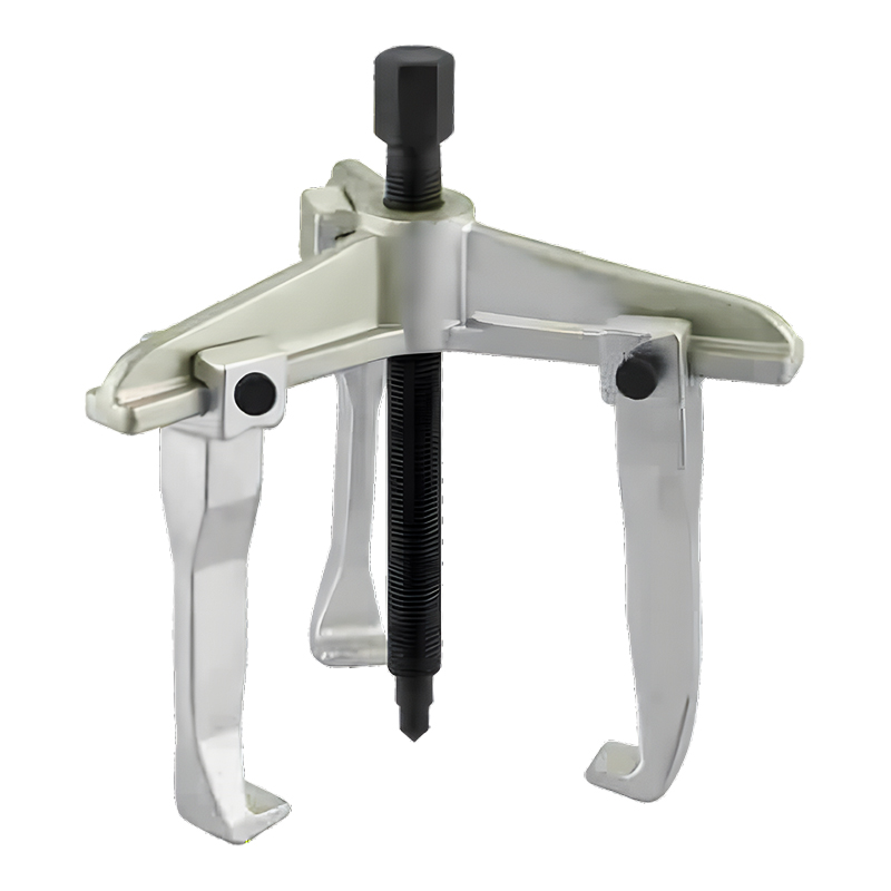
Model: SN0122
-
Model: SN0118-1
Submit feedback
Which Wheel Bearing Race Puller Is Suitable For Heavy Duty Work
2026-08-21
Removing a wheel bearing race from heavy equipment can become difficult when the ring has remained in its seat for a long period of service. Repeated loading, moisture, dirt, and surface corrosion can increase the resistance between the race and the surrounding part. A tight fit that helps keep a bearing stable during operation can therefore make later maintenance more demanding.
Wheel hub structures add another complication. A race may sit close to a shoulder, spacer, seal, or another component, leaving little room for a tool to reach behind it. A conventional puller may have nowhere safe to place its jaws. Trying to force a tool into a narrow gap can cause uneven loading, while levering against the hub or shaft can leave marks on surfaces that still need to be used.
A suitable Wheel Bearing Race Puller provides a controlled way to apply force to the race rather than transferring unnecessary pressure to nearby parts. Bearing removal guidance generally emphasizes supporting or pulling the correct fitted ring and keeping the extraction path straight, since angled loading can mark a shaft or housing.
Heavy duty work also changes the way tool selection should be approached. The question is not simply whether a puller can generate enough force. Access, gripping position, race condition, and the space available around the hub all influence whether that force can be used safely.
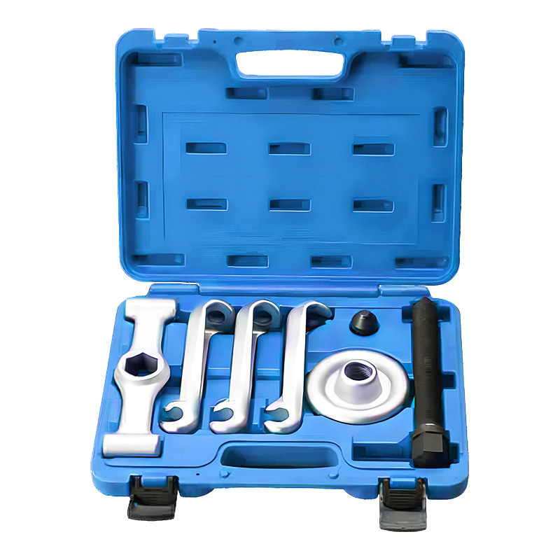
What Should Be Checked Before Choosing a Puller
A puller should be selected after examining the actual bearing arrangement. Different wheel hubs provide different access conditions, so a tool suitable for one assembly may be difficult to position on another.
Several points deserve attention before removal begins:
- Race position — Determine whether the inner race remains on the shaft or whether a race is seated inside the hub.
- Available space — Check whether enough room exists behind or inside the race for the gripping section.
- Access direction — A puller may need to enter from the front, rear, or inside the bearing.
- Grip location — The tool should contact a part of the race that can carry the pulling load.
- Condition of surrounding parts — Shaft shoulders and hub bores may need to remain usable after removal.
A bearing puller guide also separates tool selection according to whether the inner race, outer race, or another accessible surface can be gripped.
For a heavy duty wheel‑end repair, checking the assembly before applying force can prevent a common problem: choosing a tool based on the name of the component rather than the actual position of the race.
How Does an Internal Puller Grip the Bearing Race
An internal puller works from inside the bearing bore. Its gripping section enters the available opening and expands or locks against the inner race. Once a secure connection has been established, pulling force can be applied along the shaft direction.
Such a design becomes useful when the outer surface of the race cannot be reached from behind. A wheel hub may leave the inner race exposed while surrounding structures prevent ordinary external jaws from reaching a suitable gripping point.
The gripping position matters greatly. The jaws or expanding section need to engage the race firmly rather than rest against a fragile part of the bearing assembly. A poor grip can allow the tool to slip as force increases.
A controlled pulling arrangement also helps keep the load close to the center of the assembly. Straight extraction reduces the chance of the race tilting against the shaft or hub. Guidance for bearing removal similarly stresses keeping the extraction path aligned, since cocking can damage the bearing seat.
For a stubborn race, gradual force can reveal whether the tool is properly positioned. A race that begins to move evenly is generally easier to control than one that shifts sideways under load.
Which Puller Structure Fits Heavy Duty Removal Work
No single puller structure suits every wheel bearing arrangement. Internal pullers, jaw pullers, slide hammer arrangements, and separator‑based systems each solve different access problems.
| Puller Structure | Access Condition | Typical Use | Main Consideration |
|---|---|---|---|
| Internal Puller | Inner bore is reachable | Race inside a hub or restricted area | Secure internal grip |
| Jaw Puller | A rear edge is accessible | Exposed bearing surfaces | Enough room behind the race |
| Slide Hammer Puller | Direct pulling space is limited | Restricted or recessed areas | Controlled impact and grip |
| Separator Type | Little room for ordinary jaws | Tight race removal | Proper contact around the race |
An internal puller is useful when the race can be reached through its bore. A jaw design requires a suitable edge or shoulder behind the component. A slide hammer arrangement can help where a straight pulling setup is difficult to position, while a separator can create a gripping surface where ordinary jaws cannot engage.
Heavy duty applications often involve tight spaces as well as firm fits. A puller with strong construction still needs a suitable force path. Tool strength cannot compensate for poor positioning.
The intended condition of the bearing also matters. When the old bearing is already scheduled for replacement, a destructive removal method may be acceptable in some repair situations. When the component needs to remain intact, the gripping method becomes more important. Puller selection guides similarly recommend deciding whether the bearing is intended for reuse before choosing the extraction method.
How Does Pulling Force Affect Component Protection
Large removal resistance can create a temptation to increase force quickly. A more controlled approach gives greater opportunity to observe how the race and tool are responding.
The direction of force is particularly important. A puller positioned squarely with the shaft can transfer force through the intended path. An angled setup can place additional pressure on one side of the race, causing it to tilt against the shaft or hub.
For wheel hub service, protecting the surrounding surface is important because a small mark on a bearing seat can affect later assembly. Damage may also make a replacement component harder to position correctly.
A suitable setup should therefore provide:
- Stable contact between the puller and race
- A centered pulling direction
- Enough clearance for the tool to move
- No unnecessary contact with the shaft shoulder or hub surface
Once resistance begins to change, the pulling action should remain controlled rather than relying on sudden impact. Careful observation can show whether the race is moving evenly or whether the tool needs repositioning.
How Do Ultra Precision Bearings Change Removal Considerations
Ultra Precision Bearings require particular attention to the condition of the mating surfaces and the way force is transferred during service. A bearing associated with close‑fitting components can be sensitive to marks, distortion, or contamination around the installation area.
When a bearing needs to be removed without unnecessary damage, the extraction method should match the accessible race. Pulling through an unsuitable part of the assembly can place stress on components that were not designed to carry removal loads.
For precision‑related applications, a controlled removal method also makes inspection easier after the old bearing has been removed. The shaft, shoulder, and surrounding seat can be checked for marks or other changes before another bearing is installed.
The same principle applies to wheel‑end service. Heavy loading during operation does not mean that equally aggressive force should be used during maintenance. A suitable gripping position and a straight extraction path provide a more controlled route for removing a firmly seated race.
What Features Matter When Working in Tight Spaces
Limited working space changes the practical choice of a bearing puller. A wheel hub can contain several closely positioned parts, leaving only a narrow opening around the race. A tool that works well in an open assembly may become difficult to position once access becomes restricted.
Reach is one consideration. The gripping section needs to reach the race without contacting nearby surfaces unnecessarily. A long reach can help in a recessed position, while excessive length may make the tool harder to control.
Jaw or collet access also matters. The gripping section needs enough room to move into position and engage the race securely. Adjustment should remain possible after the tool has entered the assembly.
Shaft clearance deserves attention as well. A puller should not depend on the shaft shoulder or hub edge as an unintended support point. Contact in the wrong location can transfer force into a surface that needs to remain smooth for later assembly.
For tight working areas, practical checks include:
- Available entry space
- Distance to the race
- Clearance around the shaft
- Position of nearby components
- Room required for adjustment
A suitable tool should fit the assembly before force is applied. Forcing a poorly matched puller into a narrow space usually creates more problems during removal.
How Should a Puller Be Used on a Stubborn Bearing Race
A stubborn race needs a steady approach rather than repeated force without checking the setup. Before pulling, the race and surrounding area should be inspected so the gripping point can be identified clearly.
Once the puller has been positioned, the gripping section should sit firmly against the race. The tool should remain centered with the shaft, while nearby surfaces are kept clear.
A practical sequence can be kept simple:
- Inspect the assembly and identify the accessible race.
- Position the puller so the gripping section reaches a firm contact area.
- Check alignment before applying pulling force.
- Increase force gradually while watching the race for movement.
- Pause when movement becomes uneven and reposition the tool when necessary.
- Remove the race carefully once it has cleared the fitted area.
The purpose of a controlled sequence is not to make removal slower. It helps prevent a small positioning problem from becoming damage to the shaft or hub.
When a race does not move, adding force is not always the appropriate response. Rust, deformation, insufficient grip, or limited clearance may be responsible for the resistance. Identifying the cause can be more useful than simply increasing the load.
What Problems Can Occur With an Unsuitable Puller
A poorly matched tool can create problems even when the bearing itself is already due for replacement. Slippage is one common concern. When the gripping section cannot hold the race securely, pulling force may cause the tool to move away from its intended position.
Uneven loading creates another issue. A race that is pulled from one side may tilt against the shaft. Continued force can then increase friction rather than helping the component move smoothly.
Damage can also occur around the bearing seat. Marks on a shaft or hub may affect the way a replacement bearing fits later. For that reason, the surrounding surface should not be treated as a convenient place to brace the puller.
| Problem | Possible Cause | Practical Concern |
|---|---|---|
| Tool Slippage | Weak or incomplete grip | Race may remain in place |
| Uneven Movement | Pulling from an angled position | Shaft or race may be marked |
| Limited Access | Incorrect puller structure | Tool cannot reach the race properly |
| Surface Damage | Puller contacts the wrong area | Later assembly may be affected |
| Excessive Resistance | Tight fit or corrosion | More force may not solve the cause |
A tool that fits the assembly correctly can reduce the need for improvised methods. In heavy maintenance work, avoiding unnecessary contact with surrounding components is often as important as generating enough pulling force.
How Should the Right Puller Be Matched to the Application
Selection becomes clearer when the actual bearing arrangement is considered instead of relying on general equipment categories. A heavy vehicle, industrial machine, or large wheel assembly may use different bearing arrangements, so the same puller cannot automatically suit every application.
Five areas provide a practical starting point:
- Bearing Structure
The position of the race determines whether an internal grip, external jaw, or another arrangement can be used. - Working Space
A recessed race may require a puller with suitable reach and a compact gripping section. - Pulling Method
Some assemblies allow a direct mechanical pulling action, while others may require a different approach because of restricted access. - Component Condition
Corrosion, surface contamination, and long‑term loading can change how firmly the race remains seated. - Reuse Requirement
When surrounding parts need to remain in service, the removal method should avoid unnecessary marks or deformation.
A suitable Wheel Bearing Race Puller is therefore one that matches the actual contact point and available working space. The tool does not need to perform every type of removal. Its usefulness comes from fitting the particular assembly and transferring force through a controlled path.
How Can Bearing Race Removal Be Made More Controlled
Controlled removal begins before the puller touches the race. Cleaning the accessible area can make the contact position easier to see, while checking the shaft and hub can reveal damage that might otherwise be mistaken for removal resistance.
During extraction, the tool should remain stable. A race that starts moving evenly can usually be followed with gradual force. A sudden change in position, slipping grip, or sideways movement calls for a pause rather than immediate additional force.
After removal, the contact surfaces deserve a close inspection. Any marks, corrosion, or deformation should be addressed before another bearing is fitted. Keeping the installation area in suitable condition helps prevent problems during later service.
For Ultra Precision Bearings, careful handling around the fitted surfaces becomes particularly relevant. Precision‑related components rely on accurate contact between mating parts, so damage caused during removal can create difficulties that appear only during reassembly.
The same thinking applies to routine heavy duty wheel service. A suitable puller should provide enough access to grip the race, remain stable under load, and direct force through the intended path. Frame strength alone does not determine suitability.
A well‑matched tool also reduces the need for makeshift removal methods. When the race position, working space, pulling direction, and surrounding surfaces have all been considered, the removal process becomes easier to control and less likely to disturb components that need to remain in service.

-

Fax: +86-576-82686606
-

Tel: +86-576-82686563
+86-576-82686832 -

E-mail: [email protected]
-

Add: Fengjiang Industrial Park, Luqiao Area,Taizhou City, Zhejiang Province, China
Copyright © 2025 Taizhou Xinming Technology Co., Ltd. All Rights Reserved.

Sale Hardware Tools Factory