

 русский
 Español
 عربى
عربى-
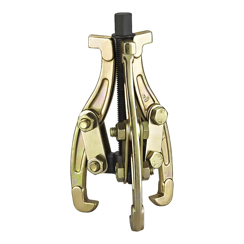
Model: SN0101
-
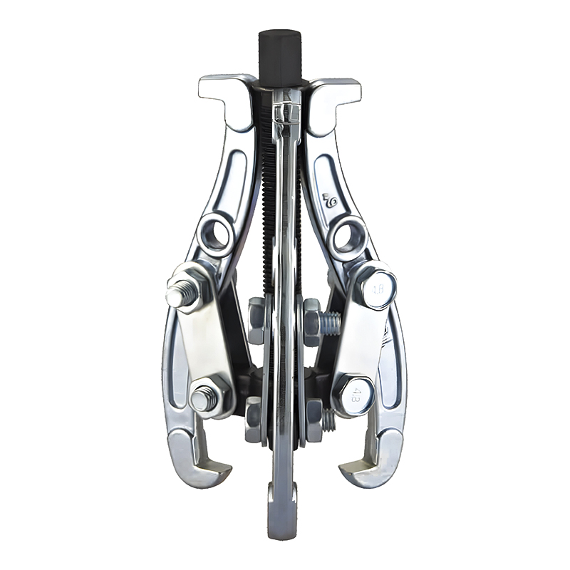
Model: SN0102-1
-
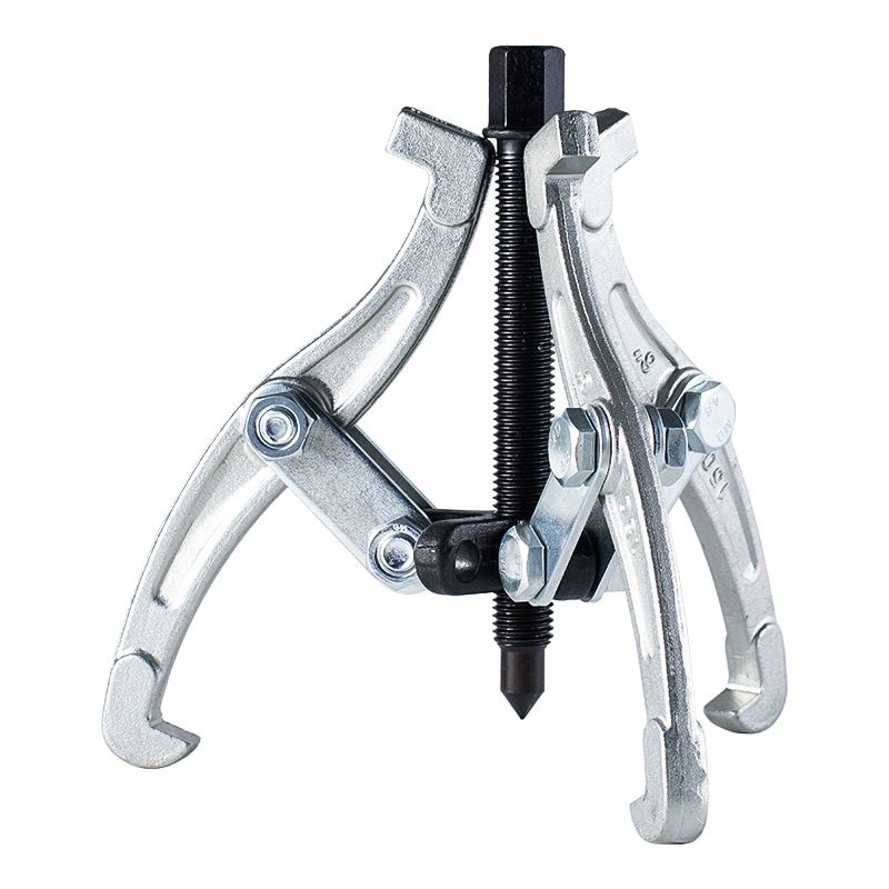
Model: SN0103
-
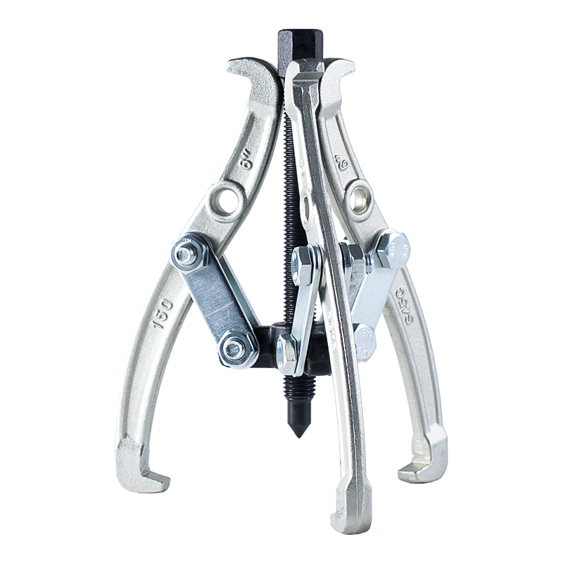
Model: SN0102 SN0107
-
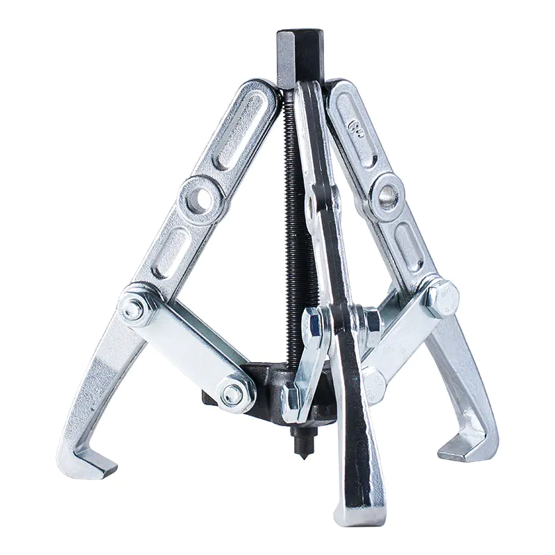
Model: SN0108 SN0109
-
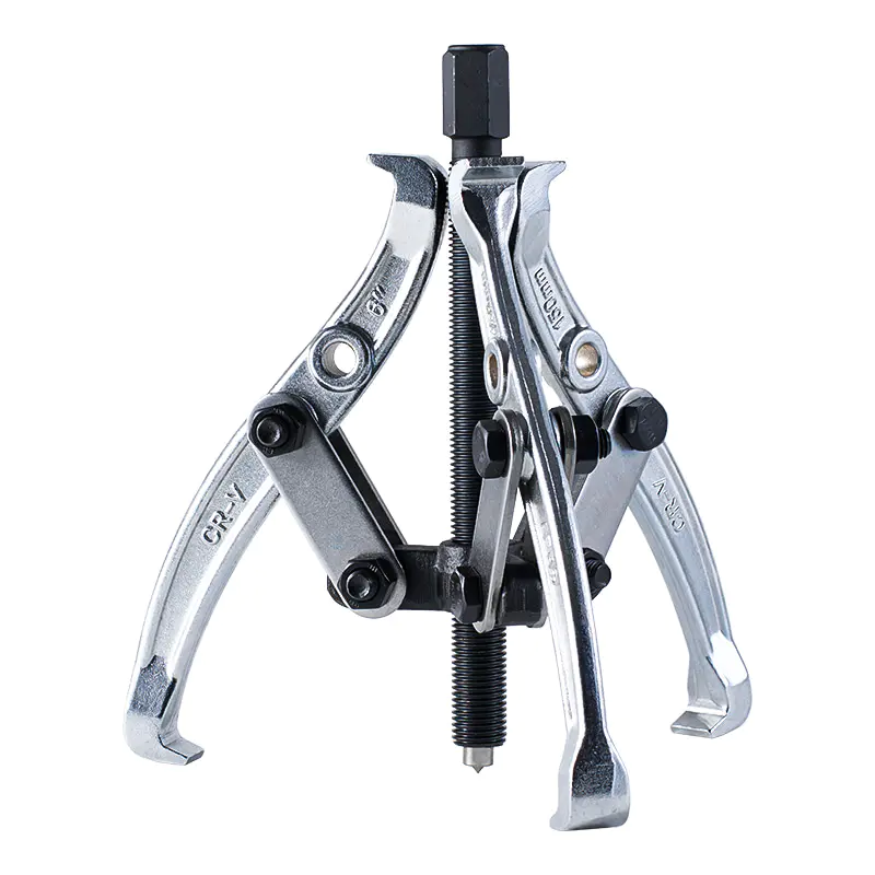
Model: SN0105
-
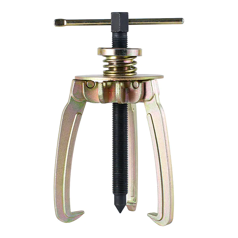
Model: SN0106
-
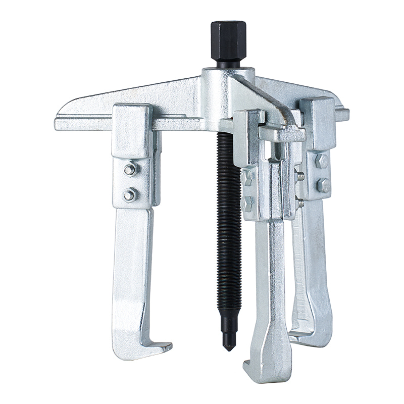
Model: SN0110
-
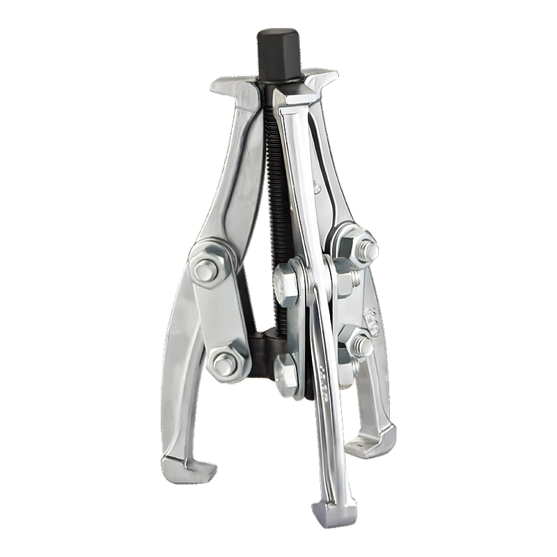
Model: SN0118
-
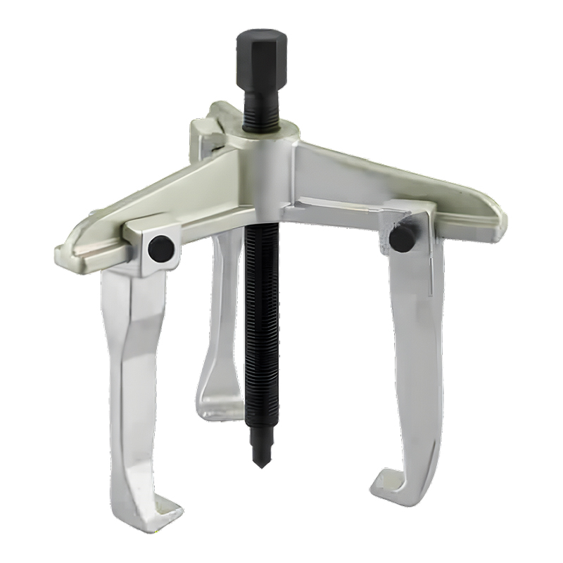
Model: SN0122
-
Model: SN0118-1
Submit feedback
What Is Puller Tool Set And How It Works In Mechanical Repair
2026-08-14
A Puller Tool Set is used when a mechanical part needs to be taken away from a shaft, housing, or another closely fitted component. Removing such parts by hand is often difficult because normal operation requires a firm connection between mating surfaces. During repair, however, that same fit can make maintenance slow and awkward.
A puller changes the way removal force is applied. Instead of hitting the component repeatedly or forcing a tool underneath an edge, a central screw and gripping arms work together to move the part gradually. Force travels through the tool toward the component, giving the technician more control over the removal process.
Gears, pulleys, hubs, and bearings are common examples. Actual suitability depends on the shape of each part and the amount of access available around it.
Several points usually need attention before choosing a tool:
- Width and shape of the part
- Position of the shaft
- Available space around the assembly
- Strength of the gripping area
- Direction in which removal needs to take place
- Condition of the component and surrounding parts
A compact part may allow simple arm positioning, while a crowded assembly can require more adjustment. Tool selection therefore starts with the mechanical arrangement rather than simply choosing a puller by appearance.
Why Are Pullers Used in Mechanical Repair
A tightly fitted part may become harder to remove after long service. Friction between surfaces can hold it in place, while dirt, residue, or corrosion may add further resistance. Sometimes a component that was easy to install becomes surprisingly difficult to remove during later maintenance.
Improvised methods can create another problem. Prying against a housing may leave marks, while striking a gear or pulley can transfer force into nearby parts. Repeated impact may also deform an edge that is needed for gripping.
Pullers provide a different approach. Gripping points hold the component while a central screw creates gradual movement. Pressure can be increased carefully while the technician watches how the part responds.
Such controlled removal is useful when a component may need to be inspected rather than discarded. A gear, bearing, or pulley might still be suitable for use after inspection, so avoiding unnecessary damage during removal can matter during routine maintenance.
How Does a Puller Tool Set Work
A basic arrangement contains a center screw, gripping arms, and a frame that keeps the parts working together. Each element has a separate function, although they operate as one system during removal.
Arms are placed around the component and adjusted until their contact points sit securely against a suitable section. The center screw is then positioned against the shaft or another stable surface.
When the screw turns, its end presses against the shaft. At the same time, the arms pull the fitted component in the opposite direction. Gradual movement continues as the screw advances.
A practical sequence is:
- Position → Align → Grip → Apply Force → Check Movement
Alignment deserves attention throughout the process. An off-center screw can make one arm carry more load than another, causing the tool to shift. A hook that moves out of position can also lose contact with the component.
For that reason, slow adjustment is usually more useful than sudden force. A part that starts moving evenly can be monitored as removal continues. Strange movement, slipping, or visible deformation indicates that the setup needs another check.
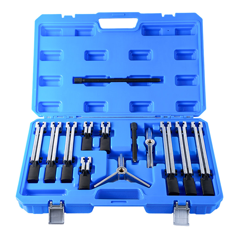
What Are the Main Parts of a Puller
Puller designs vary, although several basic components appear across different arrangements.
- Center screw
A threaded screw creates the pushing action against a shaft or stable surface. Straight positioning helps keep the pulling direction controlled. - Pulling arms
Arms reach around or behind the component. Their job is to transfer force from the frame to the part being removed. - Hooks or contact ends
Contact points need to rest against a solid area of the component. A thin edge may bend or break under pressure, so contact location matters. - Supporting frame
A frame connects the arms around the center screw and helps maintain their relative position.
| Component | Function | Inspection Point |
|---|---|---|
| Center screw | Creates pushing force | Thread condition and alignment |
| Pulling arms | Draw the part outward | Position and visible bending |
| Contact ends | Grip the component | Secure contact |
| Frame | Holds the arrangement together | Overall condition |
Cleaning and inspection are useful before each repair task. Dirt around threads can affect adjustment, while a bent arm may change the direction of applied force.
Which Mechanical Parts Can Be Removed With a Puller
Pullers are commonly associated with fitted parts such as gears, bearings, pulleys, and hubs. Shape remains an important consideration because not every component provides the same type of gripping area.
A gear with an accessible outer edge may be relatively straightforward to position. Another gear may sit close to a housing, leaving little room behind it. A bearing installed in a restricted location creates a different challenge again.
Before starting removal, technicians should check whether any retaining parts are still holding the component. Pulling against a part that has not been released can place unnecessary stress on the tool and assembly.
Working space also affects setup. Arms need enough room to reach the component and remain securely positioned. Nearby parts should not become accidental contact points for the tool.
For practical repair work, the goal is not simply to create enough force to move a stuck part. Force needs to reach the correct location and follow the intended path of removal.
How Does an Industrial Gear Puller Work on Gear Assemblies
An Industrial Gear Puller is used to remove gears from shafts during repair or inspection. Gear assemblies often require careful handling because pressure applied to the wrong area can affect teeth, shaft surfaces, or nearby components.
Arms are placed around a suitable part of the gear, while the center screw is lined up with the shaft. As pressure increases, the gear begins to move away from its fitted position.
A few checks can make the setup easier to control:
- Confirm that retaining parts have been removed
- Select solid contact points on the gear
- Keep the arms positioned evenly
- Align the center screw with the shaft
- Check hook engagement before increasing pressure
- Watch for uneven movement
When resistance remains high, applying additional force without checking the setup can create new problems. Corrosion, poor contact, remaining fasteners, or incorrect alignment may be responsible.
A careful inspection at that point can reveal whether the problem comes from the component itself or from the way the puller has been positioned.
How Should a Puller Be Positioned Before Use
Positioning has a direct effect on how pulling force reaches a mechanical part. A puller may look correctly installed from one side while an arm sits at a slightly different angle on the other side. Such small differences can become noticeable once pressure is applied.
Start by clearing dirt and loose residue around the working area. A clean surface makes it easier to see the edges of the component and identify suitable contact points.
Next, place the arms around the part. Each hook should sit against a firm section rather than a thin lip or fragile edge. Arm adjustment should leave enough contact to prevent movement during removal.
The center screw then needs to line up with the shaft. A centered position helps keep pulling force along the intended path, reducing sideways pressure on the component.
Before turning the screw, a short inspection can help:
- Are all arms sitting securely?
- Do the hooks contact similar areas?
- Is the center screw aligned?
- Could any arm touch a nearby housing?
- Has every retaining part been removed?
- Is there enough room for the component to move?
Once pressure starts, watch the tool rather than focusing only on the component. Arm movement, slipping, or tilting can indicate that the setup needs adjustment.
What Problems Can Occur When a Puller Is Used Incorrectly
Incorrect positioning can cause more than a failed removal. A hook may slip from an edge, a frame may become uneven, or force may reach a nearby part instead of the component being removed.
Uneven arm loading is one common concern. When one arm carries more pressure, the component can tilt as it moves. Gear edges may become damaged, while a shaft can receive unwanted sideways force.
Another issue appears when contact points are placed against weak sections. Thin edges may bend under pressure, leaving less room for the puller to grip. Once a contact area becomes damaged, removal can become even harder.
Excessive force can also create trouble. A stuck component may seem to require greater pressure, although resistance can have another cause, such as:
- Remaining retaining hardware
- Corrosion between mating surfaces
- Incorrect arm placement
- Poor center alignment
- A damaged component
- Insufficient working space
Stopping to inspect the arrangement is often more useful than simply increasing force. Mechanical removal should progress through controlled movement rather than a race to overcome resistance.
How Can Different Puller Designs Suit Different Repair Tasks
Pullers come in different arrangements because mechanical assemblies are not built in one standard shape. Two arms may be suitable for one component, while three arms can provide a different distribution of contact around another.
A two-arm arrangement can work where access is limited and two strong contact points are available. A three-arm arrangement can provide contact around a more rounded component, depending on the available space and tool design.
Internal and external removal also create different requirements. External pulling involves gripping around the outside of a component, while internal situations may require contact from within an opening.
Adjustable arms can be useful when component dimensions vary. Rather than placing force at a random location, arms can be positioned according to the available gripping area.
| Repair Situation | Useful Design Consideration |
|---|---|
| Open space around a part | Standard external gripping |
| Limited access | Compact arm arrangement |
| Rounded component | Multiple contact points |
| Different component sizes | Adjustable arms |
| Restricted outer edge | Alternative contact arrangement |
Tool configuration should follow component geometry. A puller that fits physically may still be unsuitable when its contact points cannot remain secure during movement.
How Should Puller Tools Be Maintained
Maintenance begins with cleaning. Metal particles, dust, grease, and residue can collect around threads and contact surfaces during repair work. Removing such material makes later inspection easier and helps keep adjustment smooth.
The center screw deserves particular attention. Threads should be checked for visible damage, contamination, or unusual wear. A screw that does not turn normally should not be forced because resistance can affect the rest of the tool.
Arms and hooks also need inspection. Bent arms can change the pulling direction, while worn contact ends may fail to hold the component securely.
After use, technicians can check:
- Center screw condition
- Arm alignment
- Hook surfaces
- Frame condition
- Thread cleanliness
- Signs of bending or cracking
Storage matters as well. Keeping parts together in a dry, organized location makes it easier to inspect the tool before another repair task. Maintenance instructions supplied with the tool should guide cleaning and any required care of moving parts.
What Should Technicians Check Before Mechanical Removal
A short inspection before removal can prevent avoidable problems. Mechanical assemblies often contain retaining elements that are easy to overlook, especially when dirt or grease covers the working area.
Start by identifying how the component is attached. Check for nuts, clips, locking parts, covers, or other features that may prevent movement.
Next, look at the space around the component. Pulling arms need room to sit behind or around the part, while the removed component needs a clear path to move.
Contact points should then be selected. Strong areas of the component are preferable to thin edges or delicate surfaces. The center screw should have a stable point against which it can apply pressure.
A practical inspection can follow a simple order:
- Confirm that the part is ready for removal.
- Clear dirt around the working area.
- Select suitable contact points.
- Position the arms evenly.
- Align the center screw.
- Check nearby components.
- Apply force gradually and observe movement.
Unusual resistance should be treated as information rather than an invitation to increase force. A second look at alignment and component condition can reveal the reason for the problem.
How Is Controlled Pulling Used in Mechanical Maintenance
Mechanical maintenance often involves removing parts that are firmly fitted during normal operation. Gears, bearings, hubs, and pulleys may need to come off for inspection, cleaning, replacement, or access to another component.
A Puller Tool Set gives technicians a way to approach removal through controlled force. Its value in repair work comes from matching the tool arrangement with the component geometry and maintaining a stable pulling direction.
An Industrial Gear Puller follows the same basic principle when working with gear assemblies. Proper arm placement, center alignment, and gradual pressure help keep removal focused on the intended part rather than surrounding components.
Tool selection is therefore closely connected with repair planning. Knowing how a component is fitted, where force can safely be applied, and how much working space is available makes the removal process easier to manage.
Good mechanical repair practice also involves knowing when to stop. A component that refuses to move may require cleaning, additional inspection, a different pulling arrangement, or another maintenance procedure rather than greater force.

-

Fax: +86-576-82686606
-

Tel: +86-576-82686563
+86-576-82686832 -

E-mail: [email protected]
-

Add: Fengjiang Industrial Park, Luqiao Area,Taizhou City, Zhejiang Province, China
Copyright © 2025 Taizhou Xinming Technology Co., Ltd. All Rights Reserved.

Sale Hardware Tools Factory