

 русский
 Español
 عربى
عربى-
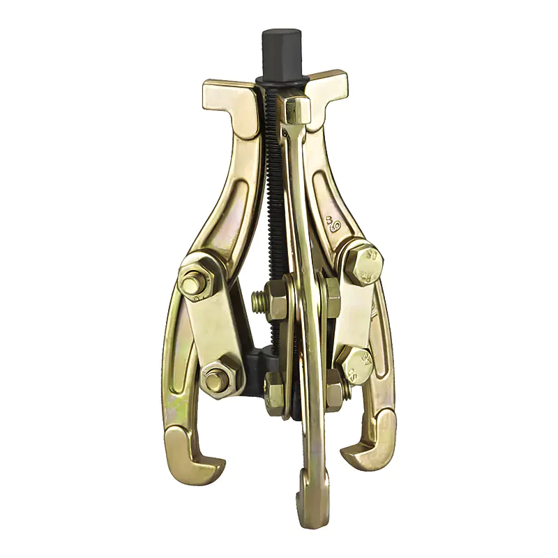
Model: SN0101
-
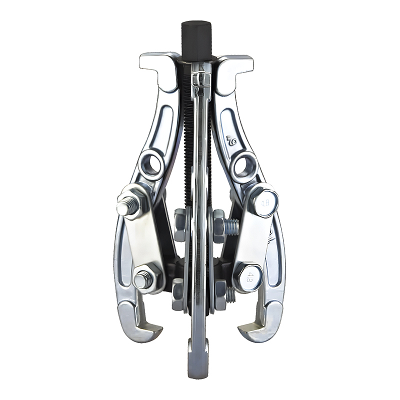
Model: SN0102-1
-
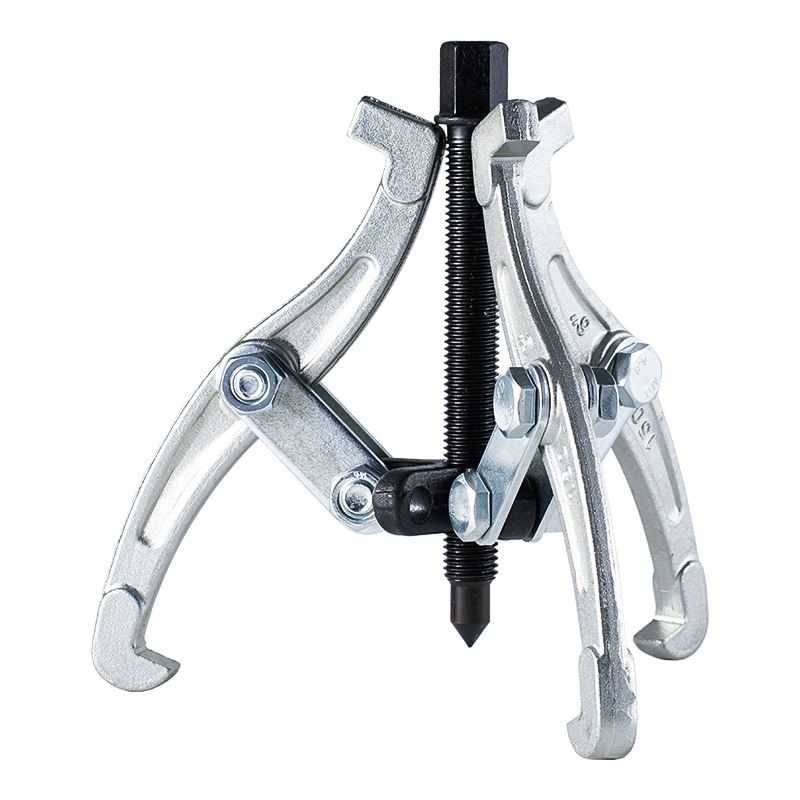
Model: SN0103
-
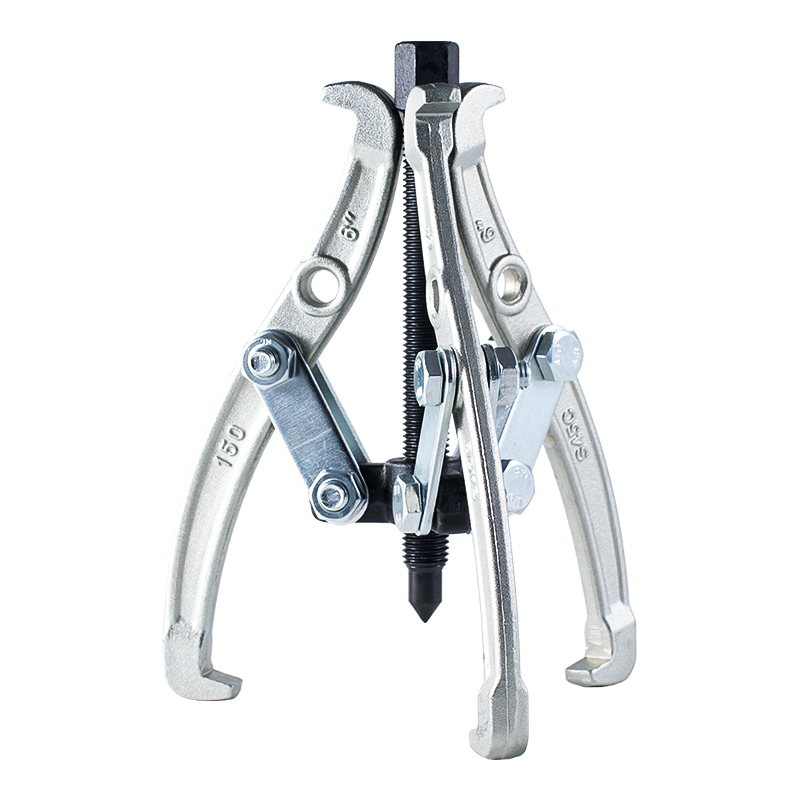
Model: SN0102 SN0107
-
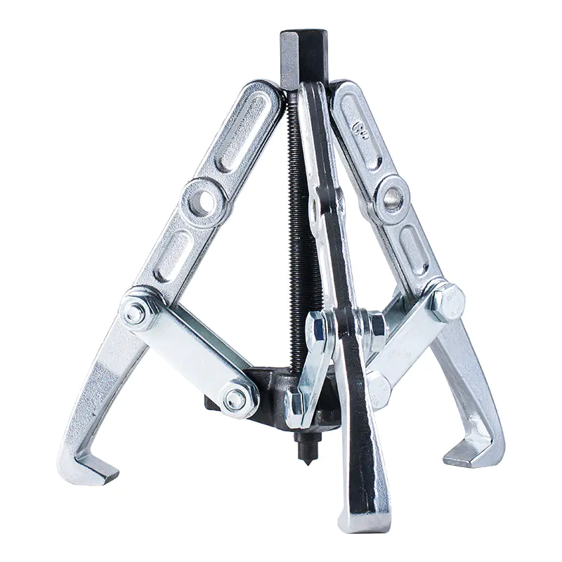
Model: SN0108 SN0109
-
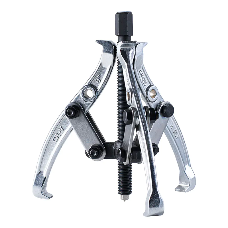
Model: SN0105
-
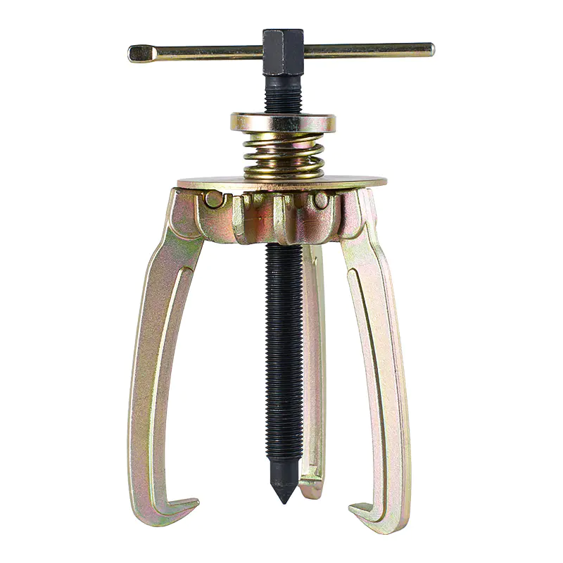
Model: SN0106
-
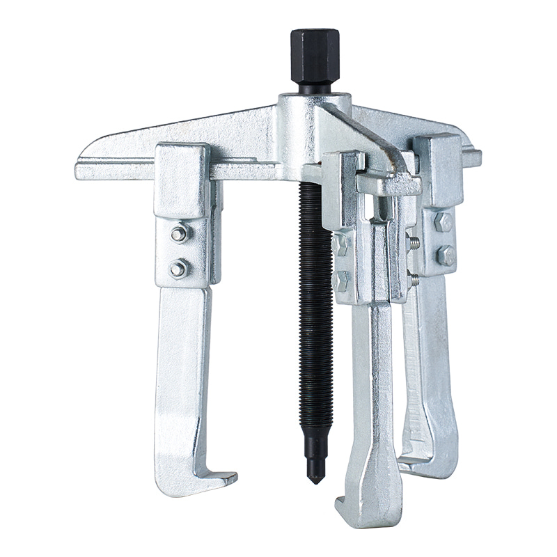
Model: SN0110
-
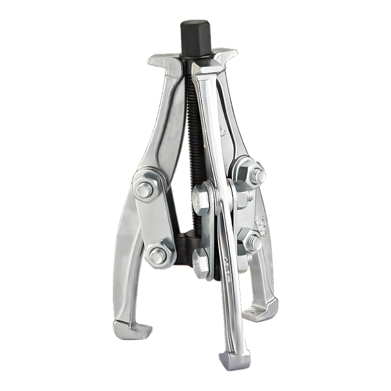
Model: SN0118
-
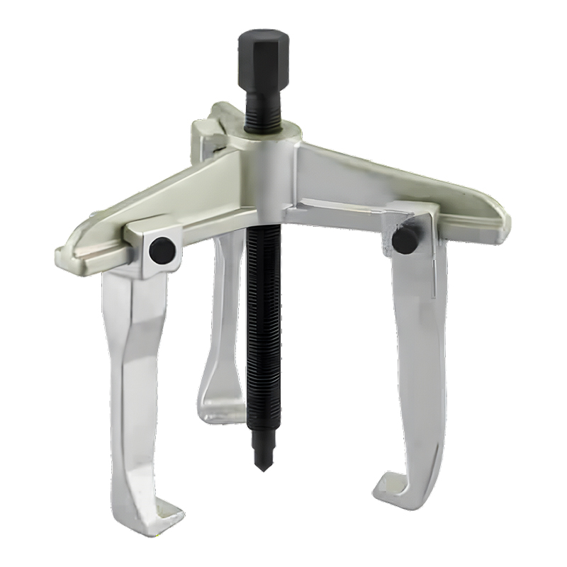
Model: SN0122
-
Model: SN0118-1
Submit feedback
Should You Choose a 2-Jaw or 3-Jaw Hydraulic Gear Puller Set
2026-09-25
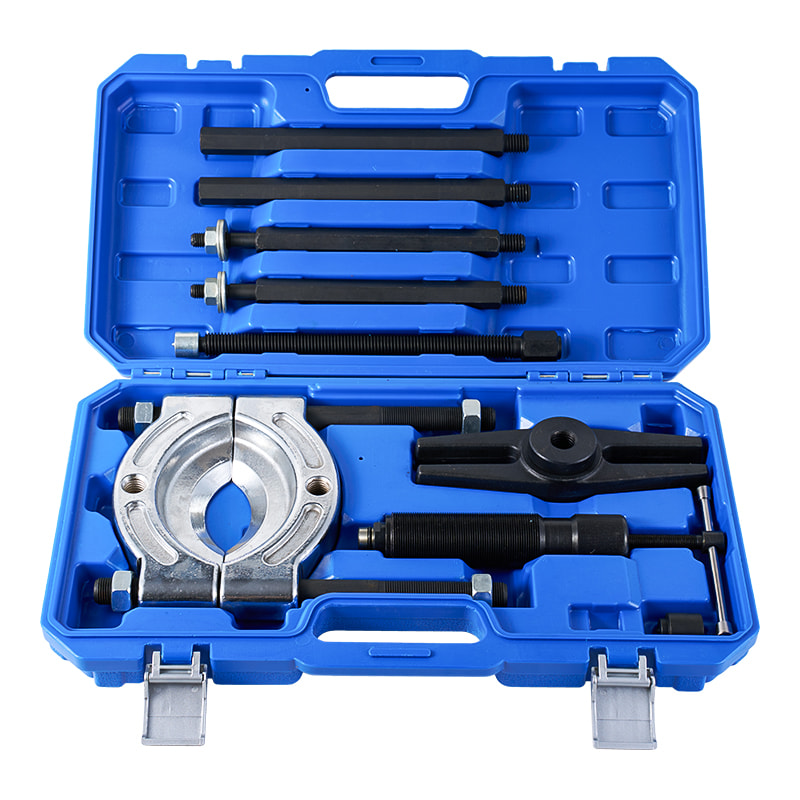
Mechanical components can become difficult to remove when they have remained in place for a long period of operation. Gears, pulleys, bearings, and similar parts may sit tightly against shafts, leaving limited space for manual removal. A hydraulic pulling tool provides controlled force while keeping the removal process centered around the relationship between the tool, the component, and the shaft.
Jaw configuration has a direct effect on that relationship. A two-jaw arrangement and a three-jaw arrangement hold a component in different ways, so the choice depends on the shape of the part, available working space, and the position from which pulling force can be applied. A suitable Hydraulic Gear Puller Set needs to match the mechanical conditions of the task rather than being selected only by the number of jaws.
Why Does Jaw Configuration Matter in a Hydraulic Gear Puller Set?
Jaw configuration determines how a component is held during removal. Each jaw needs to maintain contact with an appropriate part of the workpiece while the central pulling force acts along the shaft. When the contact points are not properly positioned, force can become uneven and the component may shift during operation.
A two-jaw design creates contact at two opposing areas. This arrangement can be useful when access around the component is restricted because fewer contact points may require less surrounding clearance. At the same time, careful positioning becomes important because the two jaws need to remain aligned with the pulling direction.
A three-jaw arrangement distributes contact around a wider part of the component. The additional contact point can help keep the workpiece positioned around the center of the pulling action. Such an arrangement can be useful when the component has a suitable outer edge that allows several jaws to engage at similar positions.
Several factors influence the choice:
- Component shape: Regular outer profiles can accommodate multiple contact points more easily.
- Available clearance: Nearby housings or other components can restrict jaw movement.
- Contact position: The jaws need a stable edge or surface to grip.
- Pulling direction: The tool should remain aligned with the shaft and workpiece.
- Surface condition: Worn, damaged, or irregular edges may affect jaw engagement.
The role of the jaw is not limited to holding the part. It also determines how force reaches the component, making configuration an important part of tool selection.
How Does a 2-Jaw Hydraulic Gear Puller Set Work?
A two-jaw puller grips the component from opposing sides while the central mechanism applies pulling force toward the shaft end. The arrangement creates a relatively open working area, which can be useful around components installed close to surrounding structures.
Positioning requires attention because the two contact points need to support the workpiece without allowing excessive movement. If one jaw sits farther from the center than the other, the component can begin to tilt as force increases. The condition of the contact edge also matters, particularly when the component has a narrow or uneven lip.
A practical setup generally involves several checks:
- Inspect the accessible edge to confirm that the jaws have a stable area to engage.
- Position both jaws evenly around the component.
- Keep the pulling point aligned with the shaft.
- Check for nearby obstructions before applying force.
- Monitor jaw contact during the removal process.
Two-jaw designs can be convenient where access is available from opposite sides but space around the remaining sides is restricted. Their relatively open arrangement may also make it easier to position the tool around components installed near a housing or frame.
The same open structure can create limitations when the workpiece requires broader support. If the component has a rounded outer profile and enough surrounding space, additional contact points may provide a different type of stability.
What Makes a 3 Jaw Hydraulic Gear Puller Different?
A three-jaw design adds another contact point around the component. Rather than relying on two opposing gripping areas, the jaws can engage at several positions around the outer edge. This arrangement can help maintain the position of a suitably shaped component while pulling force is applied through the center.
The relationship between jaw placement and the center of the workpiece remains important. Three contact points do not automatically produce balanced pulling if one jaw is positioned poorly or cannot reach a suitable surface. The component should provide enough accessible edge for each jaw to engage without slipping.
A 3 Jaw Hydraulic Gear Puller can be considered when:
- the workpiece has a relatively regular outer shape;
- several contact areas are accessible;
- stable positioning around the component is required;
- sufficient space exists for the jaws to move into place;
- the pulling direction can remain centered with the shaft.
The additional jaw can change how the load is shared between contact areas. It may also make the setup less dependent on a single opposing pair of gripping points. However, surrounding clearance becomes part of the selection process because three jaws need room to reach their respective positions.
| Selection Point | 2-Jaw Arrangement | 3-Jaw Arrangement |
|---|---|---|
| Contact Areas | Two opposing positions | Several positions around the edge |
| Space Requirement | Can suit restricted access | Requires room for additional jaw placement |
| Positioning | Careful alignment is important | Multiple contact points can support positioning |
| Suitable Shape | Accessible opposing edges | Regular outer edges with several contact areas |
| Main Consideration | Jaw balance and alignment | Contact distribution and clearance |
Where Is a 2-Jaw Puller More Practical?
A two-jaw puller can fit situations where access around a component is limited by nearby structures. Machinery often contains shafts, housings, brackets, covers, and adjacent components that leave only certain areas available for tool placement. A two-jaw arrangement may be easier to position when only opposite sides of the workpiece can be reached.
The shape of the contact edge also affects suitability. Components with a defined lip or accessible shoulder can provide a usable gripping surface. When that surface is narrow, the jaws need to remain properly seated during the pulling process.
Practical considerations include:
- clearance between the component and nearby housing;
- accessibility from opposite sides;
- condition and shape of the gripping edge;
- alignment between the tool and shaft;
- room for adjustment before pulling begins.
Two-jaw configurations can also be useful when the workpiece has an uneven outer profile that does not provide convenient positions for several jaws. In such cases, forcing additional contact points into unsuitable areas may create an unstable setup rather than improving it.
The operating environment remains important as well. A component may appear easy to reach when viewed from above, while surrounding parts restrict movement from the actual working direction. Checking the available space around the shaft and component gives a clearer basis for selecting the pulling arrangement.
When Is a 3 Jaw Hydraulic Gear Puller Suitable?
A three-jaw puller is often associated with round components, but shape alone does not determine whether it will work well. The outer edge needs to provide enough room for each jaw to sit securely. A pulley with a broad accessible rim may allow three jaws to engage evenly, while a similar-looking part surrounded by a housing may leave insufficient room for proper placement.
The position of the gripping edge matters as well. If one jaw catches a thin lip while the other two rest against deeper surfaces, the pulling force will not act evenly on the component. Movement may begin at the weak contact point as force increases.
Before selecting a 3 Jaw Hydraulic Gear Puller, several physical conditions can be checked:
- The outer edge has enough depth for secure jaw contact.
- All jaws can reach the component without touching nearby structures.
- The gripping surfaces are not badly worn or damaged.
- The shaft and component remain accessible along the pulling direction.
- No jaw needs to sit at an unusual angle to reach the workpiece.
Three contact points can be useful, but only when the component actually provides three usable contact areas. A poor contact position cannot be corrected simply by adding another jaw.
How Do Jaw Positions Affect Pulling Stability?
Many removal problems begin before hydraulic force is applied. A puller may be correctly sized for a component, yet the setup can still become unstable when the jaws are placed unevenly.
Consider a gear mounted on a shaft. If one jaw sits farther behind the gear than the others, the tool may begin pulling at an angle. The gear can then shift slightly rather than moving straight along the shaft. Contact between the jaws and the gear edge may change during removal, creating a need to stop and reposition the tool.
A simple visual inspection can reveal several warning signs:
- One jaw has noticeably less contact than the others.
- The center of the pulling mechanism does not line up with the shaft.
- A jaw is resting against a sharp or damaged edge.
- The tool body appears tilted before force is applied.
- Nearby parts prevent the jaws from sitting at similar positions.
The condition of the component should also be considered. Corrosion can make an edge brittle, while previous removal attempts may leave dents or deformation. A gripping point that appears usable at first glance may not remain secure under load.
For a Hydraulic Gear Puller Set, correct positioning is part of the removal process rather than a minor setup detail. The tool applies force to the component, but the way that force is transferred depends heavily on where the jaws make contact.
What Should Be Checked Before Choosing Between Two and Three Jaws?
Tool selection becomes easier when the component is inspected before the puller is brought into position. Measurements are not always the only concern. The shape and accessibility of the actual gripping area often determine whether a configuration can be used safely and effectively.
A maintenance inspection can follow a practical sequence:
- Look at the exposed edge. Identify the section where a jaw can make solid contact. A painted surface or rounded edge may not provide the same grip as a defined shoulder.
- Check the space around the component. A narrow gap between a gear and housing can prevent a jaw from reaching the required position, even when the front of the component appears accessible.
- Inspect the shaft alignment. The pulling point should sit in line with the shaft. An offset position can place unnecessary side force on the component.
- Check for damage. Cracks, deformation, corrosion, and previous tool marks can change the condition of the gripping edge.
- Consider the direction of movement. The component needs a clear path away from the shaft. A nearby shoulder or housing can stop movement after the initial release.
- Check jaw access before applying force. Each jaw should be able to remain seated throughout the expected movement.
Two jaws may be practical where only opposing sides are accessible. Three jaws may fit a component with several clear gripping areas. Neither arrangement removes the need to inspect the actual installation.
How Does a Hydraulic Gear Puller Set Fit Different Maintenance Tasks?
Maintenance work rarely takes place around an isolated component. Shafts may sit inside housings, gears can be close to other rotating parts, and pulleys may have limited clearance behind them. The same type of component can require a different pulling arrangement depending on its installation.
For example, a gear mounted on an exposed shaft may provide clear access around its outer edge. A similar gear inside a machine housing may leave room for only two jaws. In another case, the available edge may be uneven because part of the component is blocked by an adjacent structure.
A useful selection process can focus on the actual installation:
- Open access: Several contact points may be available, allowing a three-jaw arrangement.
- Restricted access: Opposing sides may be easier to reach with two jaws.
- Uneven outer profile: Fewer accessible gripping areas may influence the choice.
- Damaged edge: Another contact position may be needed before pulling begins.
- Limited movement space: The tool must allow the component to move without striking surrounding parts.
Routine inspection also matters after use. Jaw edges should be checked for deformation or damage, while threaded and moving parts should be kept clean and free from accumulated debris. Storage should prevent the jaws from being bent or exposed to conditions that could affect their movement.
A 3 Jaw Hydraulic Gear Puller suits situations where several secure contact points can be established around the workpiece. A two-jaw configuration can be useful when access is concentrated on opposing sides. The appropriate arrangement depends on the component, its installation, and the path available for removal rather than on jaw quantity by itself.

-

Fax: +86-576-82686606
-

Tel: +86-576-82686563
+86-576-82686832 -

E-mail: [email protected]
-

Add: Fengjiang Industrial Park, Luqiao Area,Taizhou City, Zhejiang Province, China
Copyright © 2025 Taizhou Xinming Technology Co., Ltd. All Rights Reserved.

Sale Hardware Tools Factory