

 русский
 Español
 عربى
عربى-
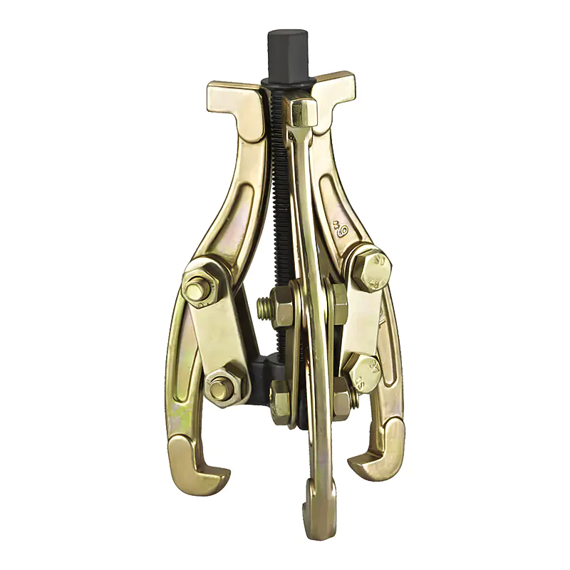
Model: SN0101
-
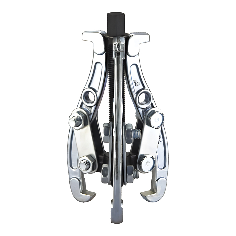
Model: SN0102-1
-
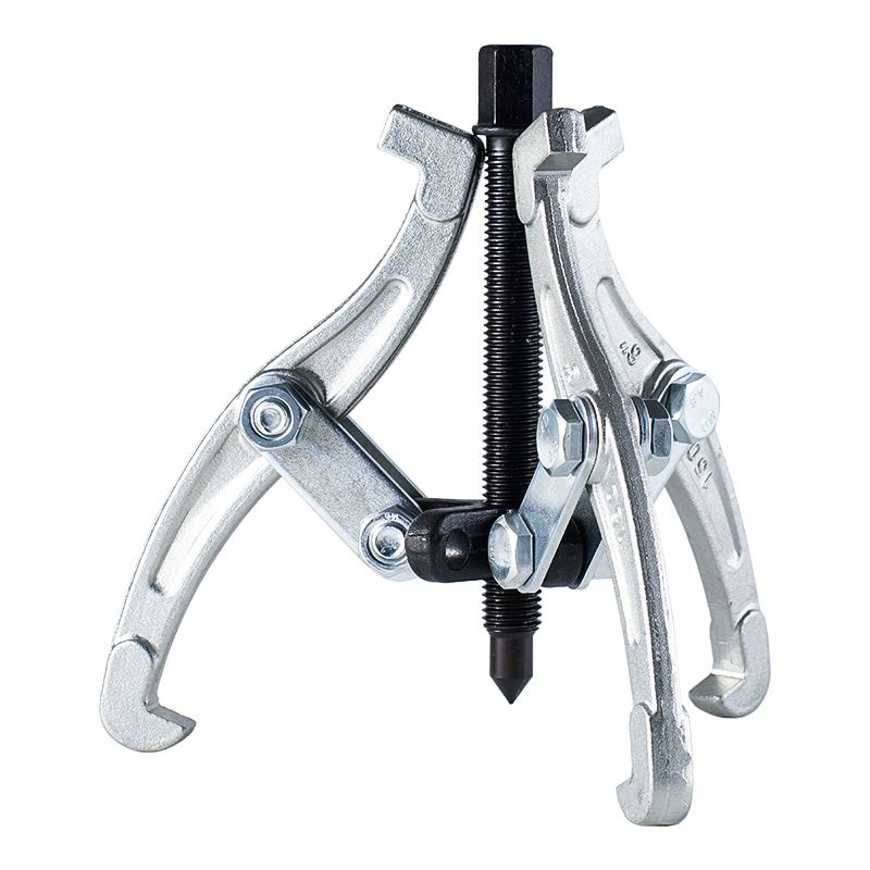
Model: SN0103
-
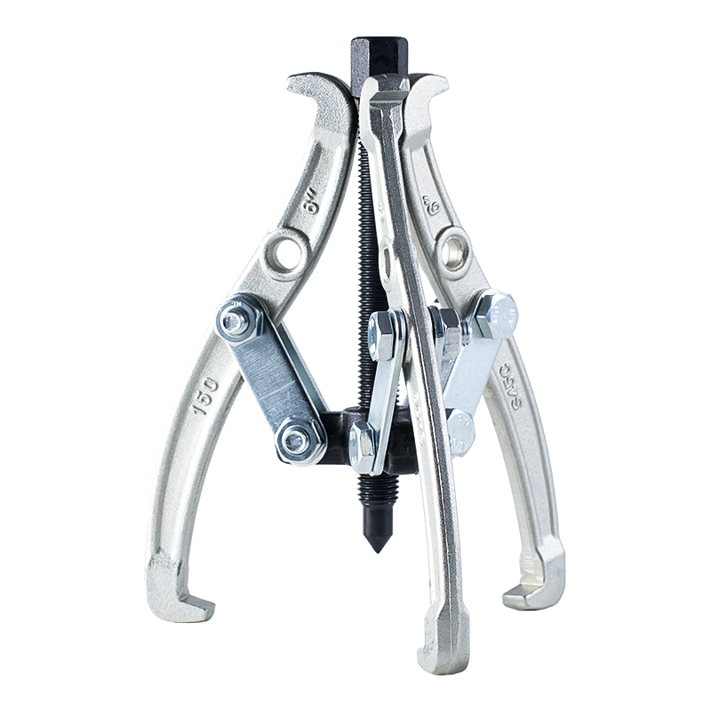
Model: SN0102 SN0107
-
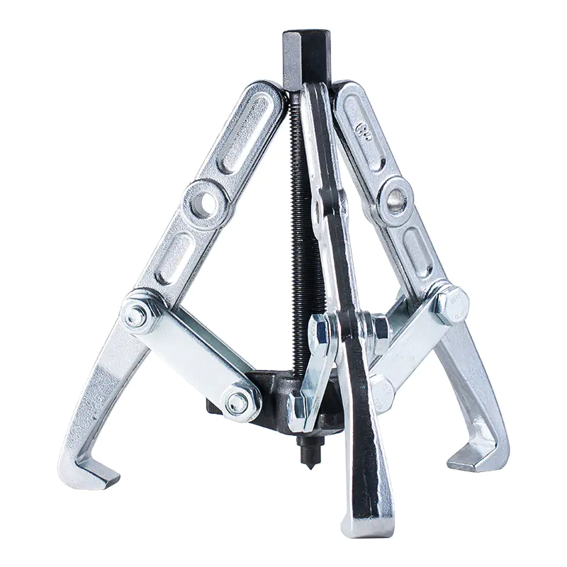
Model: SN0108 SN0109
-
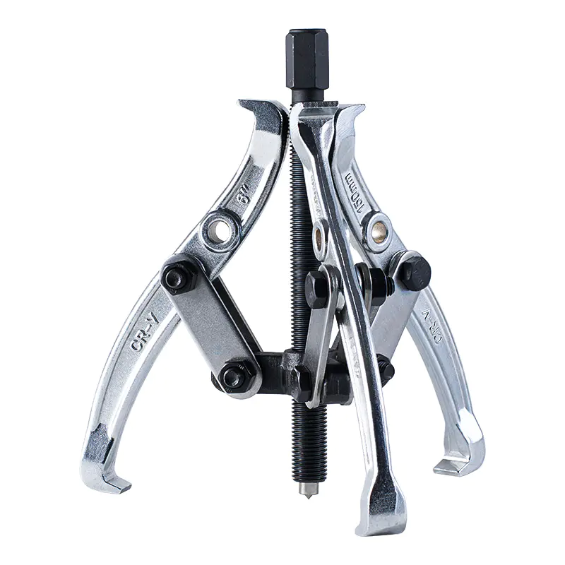
Model: SN0105
-
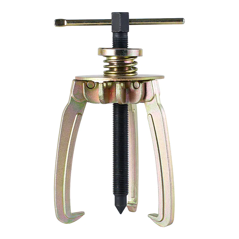
Model: SN0106
-
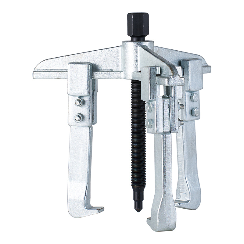
Model: SN0110
-
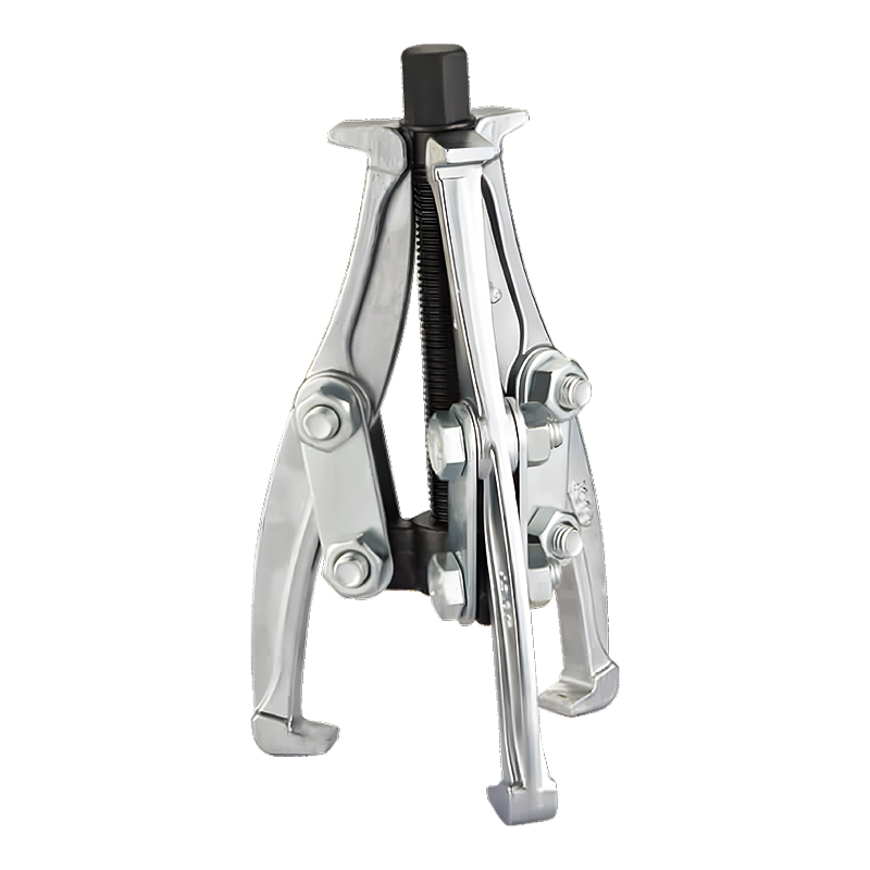
Model: SN0118
-
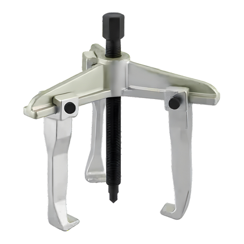
Model: SN0122
-
Model: SN0118-1
Submit feedback
Can 3 Jaw Hydraulic Gear Puller Remove Press-Fit Gears
2026-09-18
Press‑fit gears can be difficult to remove because the gear bore holds tightly around a shaft. Rust, long‑term operation, or a tight installation can add resistance when the component needs to be separated. Pulling directly on one side may cause the gear to tilt, while excessive force at a single contact point can place stress on the gear or nearby parts.
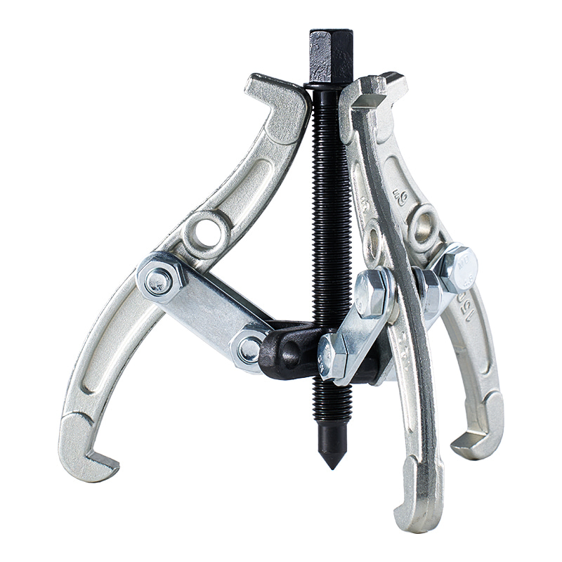
A 3 Jaw Hydraulic Gear Puller approaches the task from a different direction. Three jaws are positioned around the outer part of the gear, while a central pushing mechanism applies force toward the shaft end. As pressure increases, the jaws hold the gear and the center point pushes against the shaft, creating a controlled pulling action.
The position of the jaws matters during this process. Each jaw needs to reach a solid section behind the gear rather than resting on a thin edge or individual tooth. A suitable contact area helps keep the gear aligned as it moves away from the shaft. The available working space also needs attention because surrounding housings, bearings, covers, or other components can restrict jaw movement.
Press‑fit removal is therefore not simply a question of applying more force. The pulling direction, contact position, gear structure, and available clearance all influence how the operation proceeds. A hydraulic puller can provide adjustable force, while the three‑jaw arrangement helps distribute the load around the component.
How Does Hydraulic Force Work During Gear Removal
Hydraulic force provides the movement needed to separate a tightly fitted gear from its shaft. Instead of relying only on manual turning, the hydraulic mechanism creates pressure that moves a central piston or ram. The central point presses against the shaft while the jaws remain engaged with the gear.
As the center pushes against the shaft, the jaws transfer the resulting pulling force to the gear. Ideally, the force follows the shaft axis. When the center point is properly aligned, the gear can move outward without unnecessary sideways movement.
Several parts work together during the process:
- Central pushing point: Contacts the shaft end and provides the opposing force.
- Pulling jaws: Grip the rear or inner edge of the gear.
- Frame: Holds the pulling structure in position.
- Hydraulic mechanism: Provides controlled movement and adjustable force.
The relationship between these parts becomes important when resistance changes. A gear may move easily at the beginning and become harder to shift as contact surfaces remain tight. Gradual pressure allows the operator to observe movement rather than applying a large force immediately.
Jaw position also affects how the hydraulic force reaches the gear. When the three jaws are placed at different depths or angles, the pulling load may become uneven. The gear can then shift slightly on the shaft, making the operation less stable. Keeping the jaws at similar positions helps maintain a balanced pulling direction.
The shaft end should also provide a suitable surface for the central pushing point. A damaged, uneven, or poorly positioned shaft end can make alignment difficult. In some machinery, nearby components may also prevent the center mechanism from sitting directly on the shaft axis.
Hydraulic capacity therefore needs to match the resistance of the component being removed. Gear size alone does not determine the required pulling force. Shaft fit, corrosion, installation depth, material condition, and surrounding structure can all affect removal resistance.
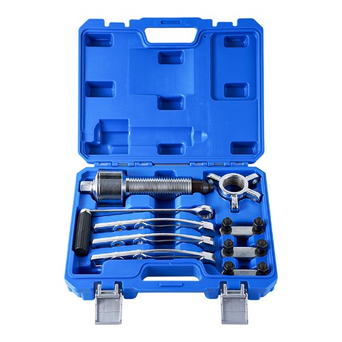
What Sizes and Capacities Come in a 3 Jaw Gear Puller Set
A 3 Jaw Gear Puller Set can contain different puller configurations intended for different gear dimensions and working conditions. The useful size is not determined only by the outside diameter of the gear. Jaw opening, working depth, frame dimensions, and hydraulic capacity all need to correspond with the actual installation.
Jaw opening determines whether the pulling arms can reach around the component. A gear may have a suitable outside diameter but still be difficult to grip when nearby housings leave little room behind it. Working depth becomes important when the gear sits farther inside a machine.
Hydraulic capacity relates to the amount of force available for separation. A larger gear does not automatically require a larger puller, while a relatively compact gear can sometimes have a tight shaft fit that creates substantial resistance. The condition of the assembly should therefore be considered alongside its physical size.
| Selection Factor | What It Relates To | Why It Matters |
| Jaw Opening | Gear outside size and available clearance | Determines whether the jaws can reach the gripping position |
| Working Depth | Gear position on the shaft | Affects access to recessed components |
| Hydraulic Capacity | Resistance during removal | Provides an appropriate force range for the task |
| Frame Size | Overall working space | Influences access around machinery |
| Jaw Contact Area | Gear structure and rear edge | Helps maintain stable engagement |
A set with several configurations can be useful when maintenance work involves gears with different dimensions. Rather than selecting a tool only by the nominal gear size, the actual installation should be checked. The distance between the gear and nearby housing may be more restrictive than the gear diameter itself.
Another consideration is how far the jaws need to extend before reaching a secure contact point. Shorter jaws may work well where the gear sits close to an exposed shaft. A deeper installation may require longer reach, provided the surrounding structure allows the puller to be positioned correctly.
Hydraulic capacity should also be considered in relation to the condition of the gear and shaft. A clean assembly with a relatively free fit may require less force than a similar assembly affected by corrosion or long‑term mechanical loading. Choosing a puller based solely on appearance can therefore overlook the actual removal conditions.
How Do Jaw Design and Frame Size Affect Gear Removal
Jaw design determines how the puller connects with the gear. The jaws need enough surface contact to remain engaged as pressure increases. A narrow or poorly positioned contact point can allow movement, particularly when the gear has a smooth outer surface or limited rear clearance.
Three jaws provide several contact points around the gear. When positioned evenly, they can help keep the component centered relative to the shaft. The arrangement is useful when the gear has a suitable rear edge that can be reached from different sides.
Jaw length also changes how the puller fits into a machine. Longer jaws can reach components located deeper inside an assembly, although the available space around the gear still determines whether they can be positioned correctly. Shorter jaws may provide a more compact setup where access is limited.
Frame size has a similar relationship with the working environment. A larger frame may provide room for a larger hydraulic mechanism, while a compact frame can be easier to position in a confined maintenance area. The physical dimensions of the machine should be checked before choosing the puller configuration.
The contact angle deserves attention as well. The jaws should engage a solid section behind the gear rather than the teeth themselves. Gear teeth are designed for transmission of rotational force, not necessarily for use as pulling surfaces. Supporting the gear from an appropriate structural area helps keep the pulling load away from delicate edges.
Once the jaws are positioned, the central pushing point should remain aligned with the shaft. The three contact points and the center force then work together around the same axis. A careful setup can reduce unwanted movement and make the removal process easier to monitor as pressure is applied.
What Should Be Checked Before Using a Hydraulic Gear Puller
A suitable puller still needs a careful setup before pressure is applied. The condition of the gear, shaft, and surrounding assembly can affect how the jaws sit and how the pulling force travels through the components.
The gear should be inspected for visible cracks, damaged edges, or areas that may not provide a secure contact surface. The shaft end also needs enough space for the central pushing point. Dirt, rust, grease, or loose material around the contact areas can affect positioning.
Several checks can be made before starting:
- Make sure the jaws reach a solid section behind the gear.
- Check that the three jaws sit at similar positions around the component.
- Confirm that the center pushing point is aligned with the shaft.
- Look for nearby housings or parts that could interfere with jaw movement.
- Keep hands and loose objects away from the moving assembly during operation.
The pulling direction deserves particular attention. A gear that is slightly tilted on the shaft may cause one jaw to carry more load than the others. Adjusting the jaw positions before applying pressure can help keep the gear centered.
The surrounding machine should also be considered. A puller may fit around the gear but still lack enough room for the hydraulic mechanism or handle movement. Access from the side, the distance behind the gear, and the position of nearby covers can all affect the setup.
Cleaning the contact area can make the inspection easier. Removing loose dirt or surface buildup helps reveal the actual edge of the gear and the shaft position. It also makes it easier to see whether the jaws are resting against a suitable structural section.
These checks are particularly useful when the gear has remained installed for a long period. A tight connection can release suddenly once resistance begins to decrease, so controlled positioning and stable support remain important throughout the operation.
How Can a 3 Jaw Hydraulic Gear Puller Reduce Damage During Removal
Gear removal involves two different concerns: separating the parts and keeping the components in usable condition. A puller cannot remove every source of mechanical stress, so the way it is positioned and operated has a direct effect on the surrounding parts.
A three‑jaw arrangement can distribute the pulling load around the gear rather than concentrating it at one side. When the jaws contact similar areas and remain aligned, the gear is less likely to rotate or tilt during movement.
The center pushing point has an equally important role. It should press against the shaft along its center line. A position that is off to one side can create additional sideways force, which may cause the gear or puller to shift.
Pressure should be increased gradually. When the gear does not move, adding force immediately may not address the actual problem. The cause may instead be an uneven jaw position, insufficient working depth, corrosion around the shaft, or contact with a nearby component.
During removal, attention can be given to:
- Jaw engagement — Check whether each jaw remains firmly connected to the gear.
- Center alignment — Keep the hydraulic pushing point in line with the shaft.
- Gear movement — Watch for uneven movement from one side.
- Pressure response — Observe whether the gear begins to separate as force changes.
- Surrounding clearance — Make sure movement does not bring the gear into another component.
The contact area after removal can also provide useful information. Marks on the gear edge may show where the jaws were positioned, while damage around the shaft end may indicate that the central pushing point was not properly aligned.
Careful removal can be particularly relevant when the gear is intended for further service. Avoiding unnecessary contact with teeth, thin edges, seals, or nearby housings reduces the chance of creating additional repair work.
Which Applications Suit Different Gear Puller Sizes
Gear pullers are used across different mechanical maintenance situations, so a single configuration may not suit every installation. The required size depends on the gear dimensions, shaft position, working depth, available clearance, and resistance during removal.
Smaller assemblies may have limited space around the gear. In these situations, a compact puller can be easier to position because the jaws and frame do not need as much surrounding clearance. The working depth still needs to reach the rear of the component.
Larger transmission assemblies can present a different set of requirements. The gear may sit farther inside a housing, while the surrounding structure limits access from one direction. A puller with greater jaw reach can provide access, provided the frame can still be positioned around the assembly.
Maintenance location also changes the practical requirements. A repair bench usually provides more room for positioning and inspection, while machinery installed in a production area may have restricted access. In a confined space, physical dimensions can matter as much as pulling capacity.
The type of component being removed also deserves attention. A puller may be used for gears, pulleys, hubs, or other press‑fitted components, yet each part can have a different contact surface. The jaws need to engage a structurally suitable area rather than simply fitting around the outside diameter.
A useful selection process can follow four basic questions:
- How wide is the component at the gripping area?
- How far behind the component must the jaws reach?
- How much room is available around the frame?
- What level of resistance is expected from the shaft connection?
These questions help connect the physical dimensions of the puller with the actual working environment. They also prevent the selection process from relying on gear diameter alone.
How Do You Choose a Suitable 3 Jaw Gear Puller Set
Choosing a 3 Jaw Gear Puller Set involves matching the tool configuration with the components that need to be removed. A set containing different jaw arrangements or sizes can provide flexibility for maintenance work involving several types of assemblies.
Jaw opening is one of the basic factors. The jaws need to extend around the component without forcing contact against nearby machine parts. Working depth should then be checked to make sure the jaws can reach a secure area behind the gear.
Hydraulic capacity is another consideration. The required force depends on the relationship between the gear and shaft, rather than on gear diameter alone. Corrosion, surface condition, installation pressure, and operating history can all influence resistance.
Frame dimensions should also fit the available working space. A puller that has suitable capacity may still be difficult to use when the frame cannot pass around a housing or when the jaws cannot reach the required position.
For maintenance teams, a practical configuration may be based on the range of components handled regularly. Several compatible sizes can reduce the need to adapt one puller to installations outside its intended working range.
Before selecting a set, it is useful to compare:
- Opening range with the actual gear or component width
- Working depth with the installation position
- Hydraulic capacity with expected removal resistance
- Frame dimensions with available machine clearance
- Jaw shape with the contact area behind the component
The condition of the tool should also remain part of routine maintenance. Hydraulic components, jaws, threads, contact points, and frame connections need inspection before repeated use. Wear at the gripping surfaces can change how securely the jaws hold the component.
For press‑fit gear removal, tool selection and operating technique are closely connected. A suitable opening range does not compensate for poor alignment, while adequate hydraulic force does not replace stable jaw placement. The combination of correct dimensions, secure contact, controlled pressure, and enough working space determines how effectively the puller can perform its intended task.
When these factors are considered together, 3 Jaw Hydraulic Gear Puller selection becomes less about choosing a tool by appearance and more about matching the puller to the actual mechanical arrangement. The same approach also helps when comparing different configurations within a 3 Jaw Gear Puller Set, particularly when maintenance work covers gears and other press‑fitted components with different dimensions.

-

Fax: +86-576-82686606
-

Tel: +86-576-82686563
+86-576-82686832 -

E-mail: [email protected]
-

Add: Fengjiang Industrial Park, Luqiao Area,Taizhou City, Zhejiang Province, China
Copyright © 2025 Taizhou Xinming Technology Co., Ltd. All Rights Reserved.

Sale Hardware Tools Factory