

 русский
 Español
 عربى
عربى-
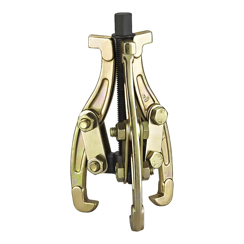
Model: SN0101
-
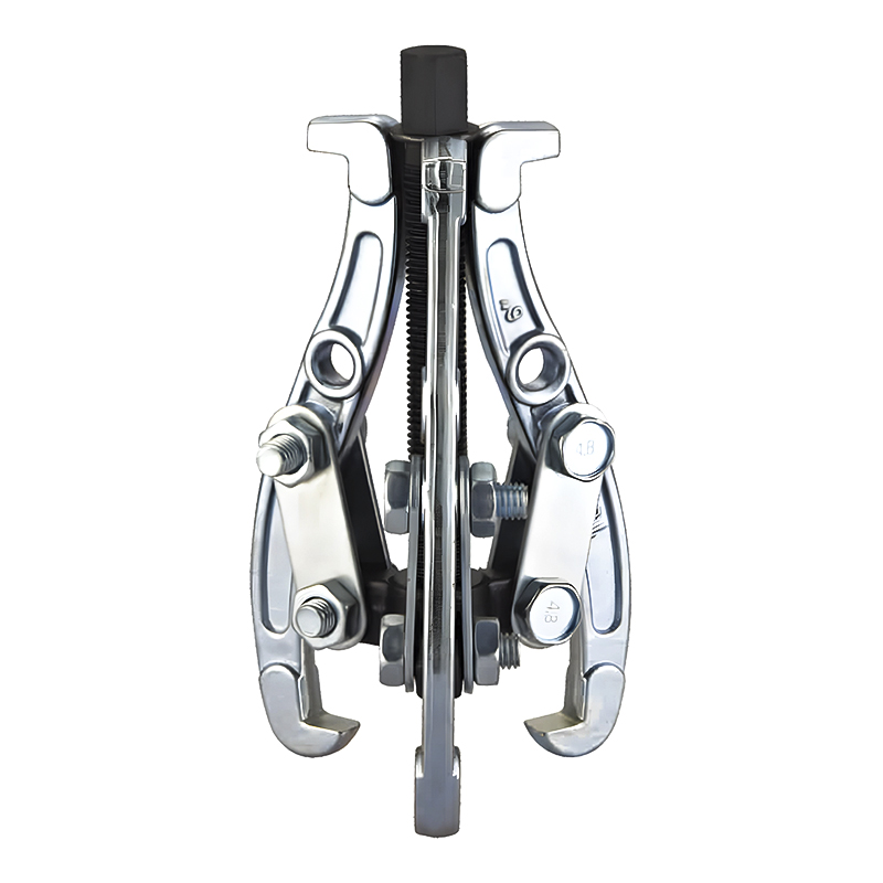
Model: SN0102-1
-
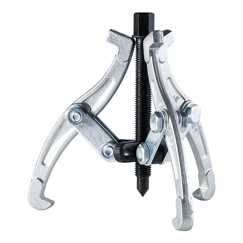
Model: SN0103
-
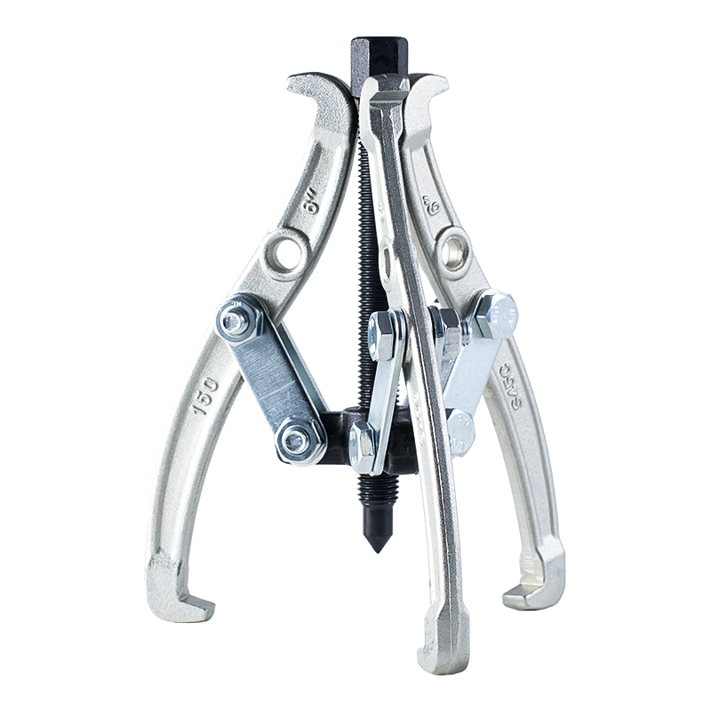
Model: SN0102 SN0107
-
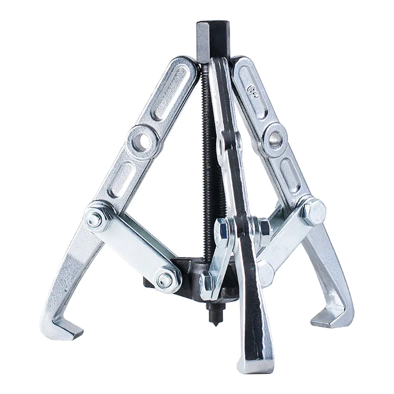
Model: SN0108 SN0109
-
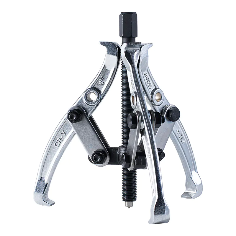
Model: SN0105
-
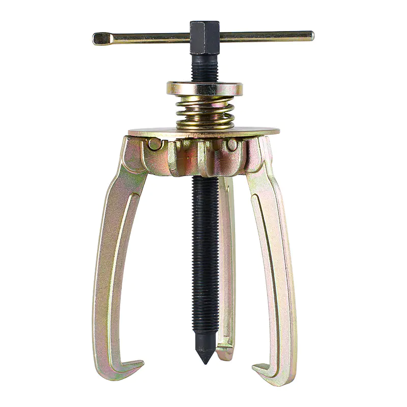
Model: SN0106
-
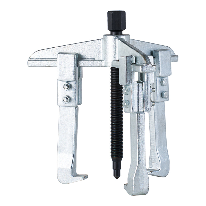
Model: SN0110
-
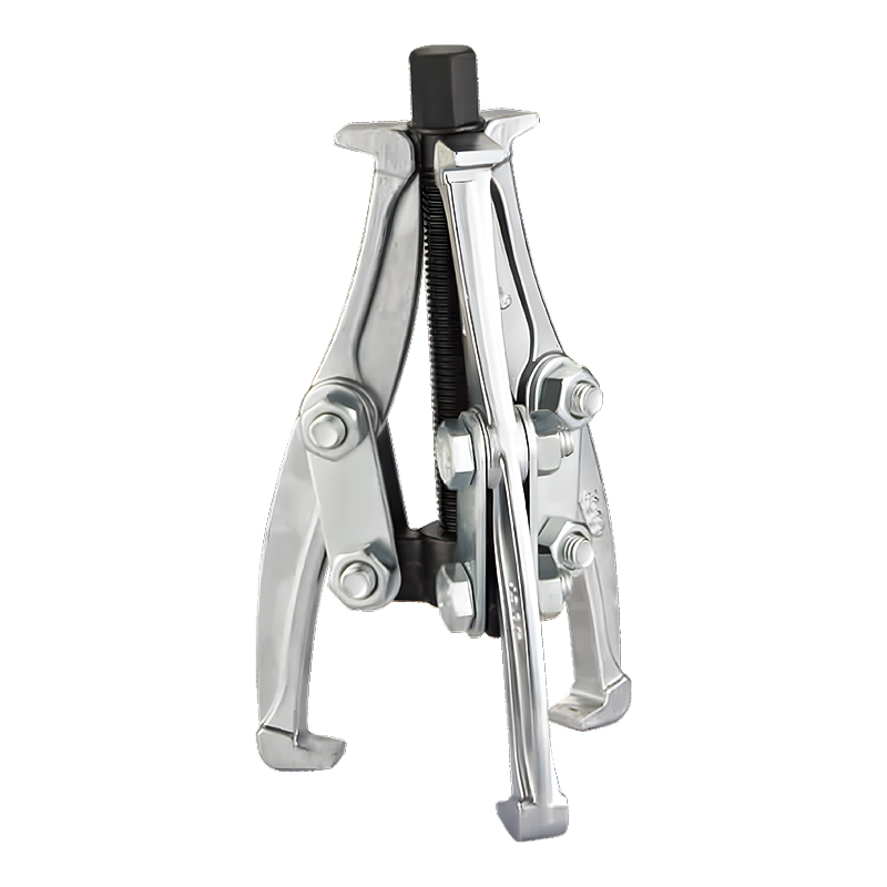
Model: SN0118
-
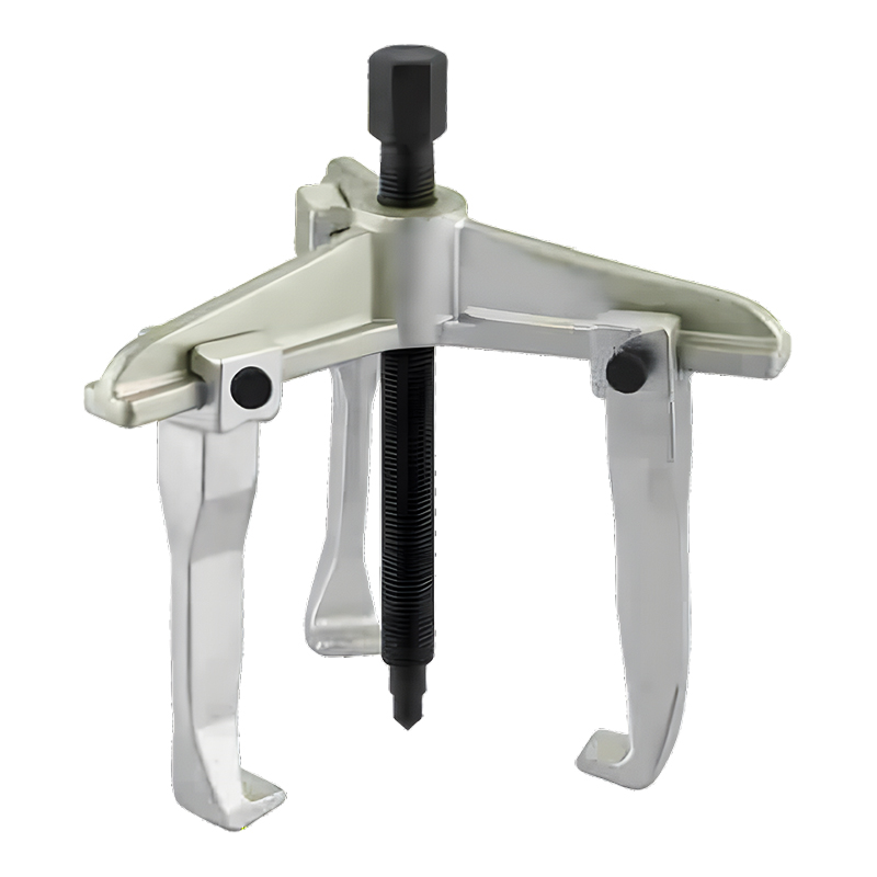
Model: SN0122
-
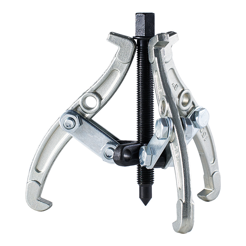
Model: SN0118-1
Submit feedback
How Does 2 Jaw Puller Set Remove Tight Fitted Components Safely
2026-05-29
In many mechanical environments, tight fitted components are not unusual. Gears, bearings, and similar parts often sit on shafts with strong contact pressure. Over time, that contact becomes more rigid than expected. Surface friction increases, and small deformation between contact layers slowly builds up resistance.
In practical maintenance work, removal does not feel simple. A component that once slid into place can later feel almost fixed. The reason is rarely visible from outside. Pressure distribution inside the fitting area changes after long use, and that change makes separation harder.
Attempts using direct force often create problems. Hammering or prying introduces uneven impact. One side receives more stress than the other. That imbalance leads to scratches or bending marks on the shaft surface. In sensitive assemblies, even a small mark can affect later movement.
Because of these conditions, a controlled pulling method becomes necessary. Instead of impact force, steady mechanical tension allows parts to separate in a more predictable way. The 2 jaw puller set is designed around this idea.
What Defines The Working Structure Of A 2 Jaw Puller Set
A 2 jaw puller set is built around a simple mechanical layout. Two arms extend outward and grip the edge of a component. At the center, a forcing screw sits aligned with the shaft. Together, these parts create a controlled pulling path.
The two jaws work as a balanced pair. Each side holds the component at opposite points, creating equal force distribution. The central screw then applies pressure inward, converting rotational movement into linear pulling force.
In actual use, the movement feels gradual rather than sudden. As the screw turns, tension builds slowly. The component begins to shift along the shaft axis instead of breaking loose abruptly.
Key structural roles:
- Two jaws: hold and stabilize the component
- Central screw: generates steady pulling force
- Contact points: maintain alignment during load
- Shaft tip contact: anchors pulling direction
The combination allows removal without relying on shock force.
How Even Force Distribution Helps Prevent Surface Damage
Surface damage during removal often comes from uneven stress. When pressure concentrates on one side, the component tilts slightly. That tilt creates friction against the shaft surface.
A 2 jaw puller set avoids this situation through symmetrical grip. Both jaws sit at opposite sides, typically around a 180-degree balance. That layout keeps the component aligned with the shaft axis.
When force is applied evenly, the part moves in a straight line. No side drags more than the other. The surface contact remains controlled, which reduces the chance of scratches or edge gouging.
A simple comparison helps illustrate the difference:
| Method | Force Behavior | Movement Type | Surface Risk |
|---|---|---|---|
| Hammer impact | Sudden and uneven | Jerky release | Higher chance of marks |
| Pry tools | Single-direction pressure | Angular shift | Edge damage likely |
| 2 jaw puller set | Balanced and steady | Linear pull | Lower surface stress |
The balanced approach is not about speed. It is about keeping motion aligned with the shaft center.
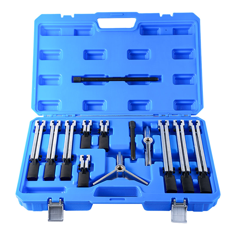
How The Central Forcing Screw Controls Pulling Motion
The central screw is the driving point of the entire system. Rotational input is applied by hand or tool, and that rotation becomes forward pressure along the shaft axis.
Each turn increases tension slightly. The component does not move instantly. Instead, it responds to accumulated force. This gradual response allows the material to adjust before separation begins.
One important detail is consistency. Sudden force spikes are avoided because the screw translates motion in a controlled path. The pressure builds step by step rather than in a single impact.
During operation, the screw also acts as a stabilizer. It keeps the puller centered and maintains alignment between jaws and shaft. Without this control, movement would become uneven and harder to manage.
The slow conversion of force is what makes the system suitable for delicate surfaces.
Why Alignment Directly Affects Removal Quality
Alignment plays a quiet role but determines whether removal feels smooth or unstable. When jaws are slightly off center, the pulling direction shifts. Even a small deviation can increase resistance on one side.
Proper alignment means the screw tip sits directly on the center point of the shaft. Many shafts have a small indentation or flat center area designed for this purpose. Once the screw rests there, force travels in a straight line.
Misalignment leads to side pressure. That side pressure creates uneven friction. Over time, it can cause light scoring on the surface or uneven release of the component.
A stable setup usually follows a simple sequence:
- jaws placed evenly around component
- screw aligned with shaft center
- no visible tilt before tightening begins
When these conditions are met, pulling motion stays predictable.
Preparing The 2 Jaw Puller Set Before Use
Before any removal begins, tool preparation influences the entire process. The forcing screw threads are often lightly lubricated. This reduces internal friction during rotation and allows smoother torque control.
Dry threads tend to resist movement under load. That resistance can affect control during tightening. Light lubrication keeps motion steady.
Jaws are also checked for fit. The opening must match the edge of the component. If contact points are too shallow, slipping may occur during tension buildup.
Simple preparation steps:
- apply light lubrication on screw threads
- confirm jaw opening matches component size
- check jaw symmetry before placement
- ensure screw turns smoothly without resistance
Preparation often decides how stable the later steps feel.
Proper Hooking Position On Tight Fitted Components
Correct jaw placement is essential. The jaws should hook behind the edge of the component, not on a weak or slanted surface. Contact must feel firm on both sides.
In mechanical fittings like gears or bearing housings, edges vary slightly. Some areas are stronger, others more fragile. Choosing a stable gripping point reduces slipping during pull.
Once positioned, both jaws should appear evenly spaced. Uneven placement often leads to tilting once force is applied.
A small practical check:
- both jaws touch at equal depth
- no visible angle between jaws and shaft
- component remains centered before tightening
At this stage, no force should be applied yet. Position stability matters more than pressure.
Centering The Forcing Screw On Shaft End
After jaws are placed, the central screw is brought into contact with the shaft end. Most shafts have a small center mark or flat point. That area helps guide the screw tip into position.
The screw should rest directly in that point. Once seated, the pulling direction aligns with the shaft axis.
If the screw sits off-center, force shifts sideways. That shift increases resistance and affects surface contact quality.
Proper centering keeps the system balanced before tension begins.
Applying Steady Mechanical Tension During Pulling
Once alignment and positioning feel stable, the next stage is gradual force application through the central screw. In real maintenance work, this step often determines whether the removal process stays smooth or becomes unstable.
The screw is turned slowly. Each small rotation adds tension to the jaws. The component does not move immediately. Instead, it responds to accumulated pressure along the shaft axis. That slow response is important, because sudden movement usually leads to surface stress.
During this stage, the puller should remain steady. Any shift in angle can change the direction of force. Even slight tilting increases friction on one side of the component.
A practical observation in workshop conditions is that smooth removal rarely comes from force speed. It comes from controlled rhythm. Turning, pausing, checking alignment, then continuing again is a common pattern.
Key points during tension application:
- rotation stays slow and even
- tool position remains level
- jaw grip is checked during pauses
- no sudden torque increase is applied
The component usually begins to move in small increments. That movement may not be visible at first, only felt through reduced resistance in the screw.
Managing High Resistance or Stuck Components
Some components resist movement even after correct setup. In those cases, increasing force alone is not a safe approach. The structure of the puller is designed for steady load, not sudden overload.
When resistance feels high, a short pause often helps. Pressure is maintained at a steady level without additional tightening. In many situations, that constant tension allows internal friction to start breaking gradually.
Another common approach is light vibration assistance. A soft mallet may be used to gently tap near the component or shaft area. The vibration travels through the fitted surfaces and helps loosen static friction bonds.
Important point here is control. The tapping is light, not forceful. The puller remains under tension during the process, which keeps the pulling direction stable.
Typical handling approach:
- maintain steady tension without over-tightening
- apply light vibration near fitted area
- avoid sudden torque increases
- allow time for gradual movement
In many maintenance cases, components begin to release after a short cycle of steady load and light vibration.
How Surface Protection Is Maintained Throughout Removal
Surface protection during pulling does not come from one single action. It comes from several small conditions working together during the process.
Even force distribution ensures that no single point carries excess load. This reduces the chance of surface indentation on the component edge. When both jaws remain balanced, movement stays aligned with the shaft.
The central screw also plays a protective role. Because force travels directly along the shaft axis, stress remains concentrated in the intended direction rather than spreading sideways.
Another important factor is speed control. Slow pulling avoids sudden separation, which is often the moment where surface marks occur.
Protection logic in practice:
- balanced jaw contact reduces edge stress
- centered screw maintains axial direction
- slow tension prevents sudden release
- stable grip avoids sliding friction
Together, these factors allow the component to move gradually instead of breaking free abruptly.
Common Mistakes That Lead To Damage During Pulling
Even with a proper tool, surface damage can still happen when small mistakes occur during setup or operation. Most issues come from alignment or force control rather than tool design.
One frequent issue is uneven jaw placement. If one jaw grips deeper than the other, force becomes unbalanced. That imbalance leads to tilting during pulling.
Another issue is skipping lubrication on the screw. Dry threads increase resistance, which can cause sudden movement when force finally releases.
Incorrect centering of the screw is also a common cause of surface marks. When the screw is not aligned with the shaft center, side pressure builds up during tightening.
Typical mistakes:
- uneven jaw grip depth
- off-center screw contact
- rapid tightening without checks
- dry screw threads under load
Each of these can affect stability and increase surface contact stress.
Why 2 Jaw Puller Set Works Well In Limited Space Areas
In many maintenance environments, space around components is limited. Some parts are installed close to walls, housings, or other mechanical structures. In such cases, tool size and movement freedom become important.
A 2 jaw puller set has a compact structure compared to multi-jaw alternatives. With only two contact points, positioning requires less clearance. This allows access to components that sit in tighter assembly spaces.
The design also allows easier rotation of the forcing screw. Less surrounding obstruction means smoother tool handling during tightening.
In practice, this makes the tool suitable for:
- narrow mechanical housings
- closely packed shaft assemblies
- small rotating components
- confined maintenance zones
The simpler structure does not limit control. Instead, it reduces space interference during operation.
How The Tool Fits Into Routine Maintenance Work
In daily maintenance workflows, removal tools are not used in isolation. A 2 jaw puller set is usually part of a sequence of steps involving inspection, cleaning, and replacement.
The puller often appears after initial inspection confirms tight fit conditions. Once used, it becomes part of the disassembly stage before cleaning or part replacement.
In repeated maintenance cycles, familiarity with the tool becomes important. Operators often develop a sense of how much tension is needed before movement begins, based on component behavior rather than force measurement.
Typical workflow placement:
- inspection of fitted component
- preparation and tool setup
- controlled removal using puller
- post-removal surface check
- next-stage maintenance tasks
Within this flow, the puller serves as a controlled separation tool rather than a force-driven device.
Why Controlled Mechanical Pulling Remains Reliable In Practice
Mechanical systems often respond better to gradual force than sudden impact. Tight fitted components are no exception. The structure of the 2 jaw puller set supports this idea by converting simple rotation into steady linear movement.
What makes the method stable is not complexity, but control over direction and pressure. Every part of the system contributes to keeping force aligned with the shaft axis.
In real use, the process feels repetitive but predictable. Position, align, tighten slowly, pause, adjust, continue. That rhythm reduces the chance of surface damage and keeps removal behavior consistent across different component types.
In workshop conditions, the 2 jaw puller set is not treated as a complicated instrument. It is used in a straightforward way, following a clear pattern of placement and controlled tightening.
The tool performs quietly during operation. Movement is gradual, force is steady, and separation happens step by step rather than suddenly. When used with proper alignment and pacing, the interaction between tool and component remains controlled.
Over time, repeated use builds familiarity with how tight fittings respond under steady pull. That experience becomes part of routine mechanical handling, especially in environments where precision and surface protection matter during disassembly work.

-

Fax: +86-576-82686606
-

Tel: +86-576-82686563
+86-576-82686832 -

E-mail: [email protected]
-

Add: Fengjiang Industrial Park, Luqiao Area,Taizhou City, Zhejiang Province, China
Copyright © 2025 Taizhou Xinming Technology Co., Ltd. All Rights Reserved.

Sale Hardware Tools Factory