

 русский
 Español
 عربى
-
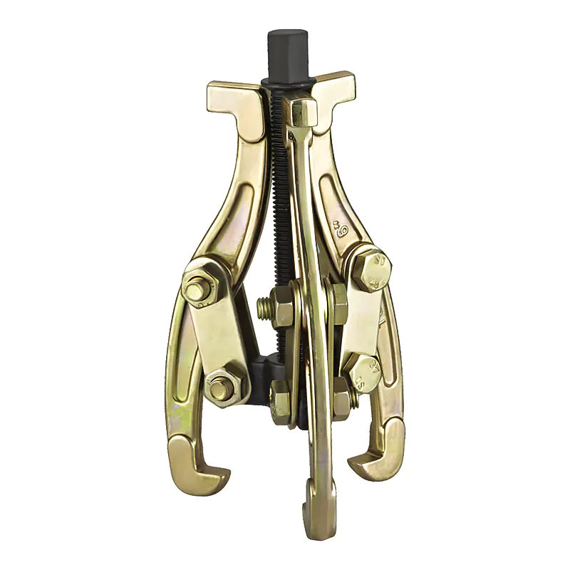
Model: SN0101
-
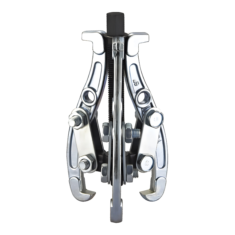
Model: SN0102-1
-
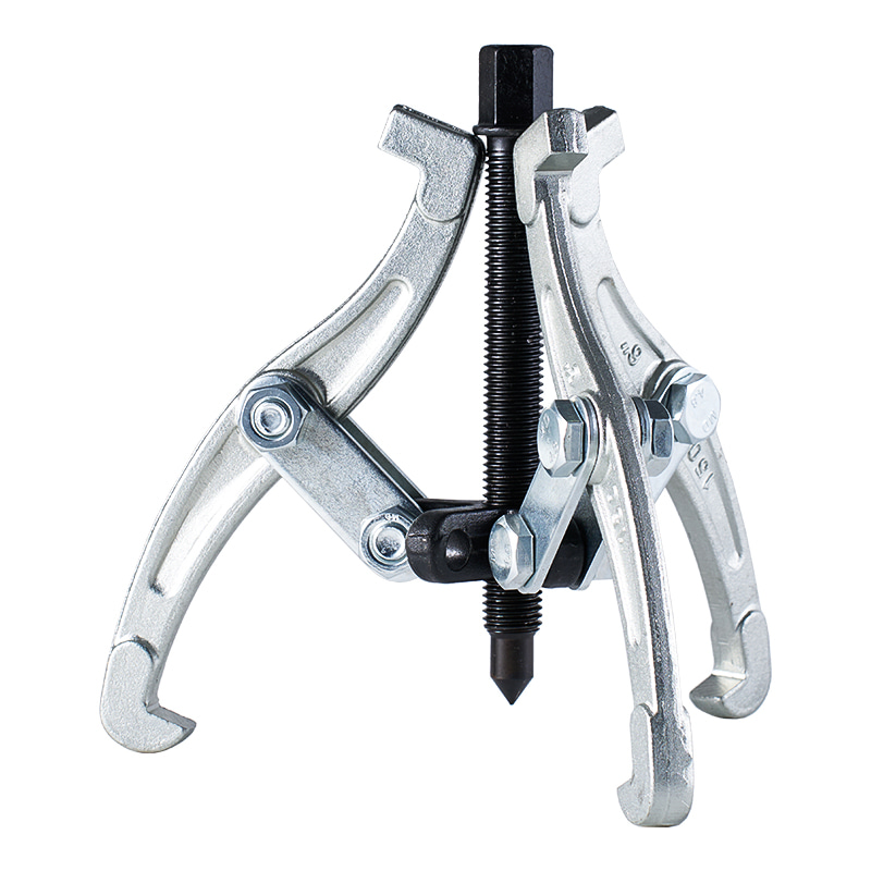
Model: SN0103
-
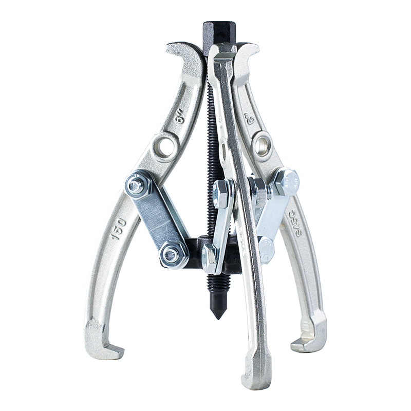
Model: SN0102 SN0107
-
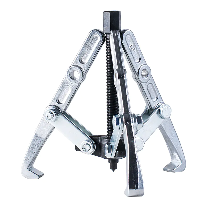
Model: SN0108 SN0109
-
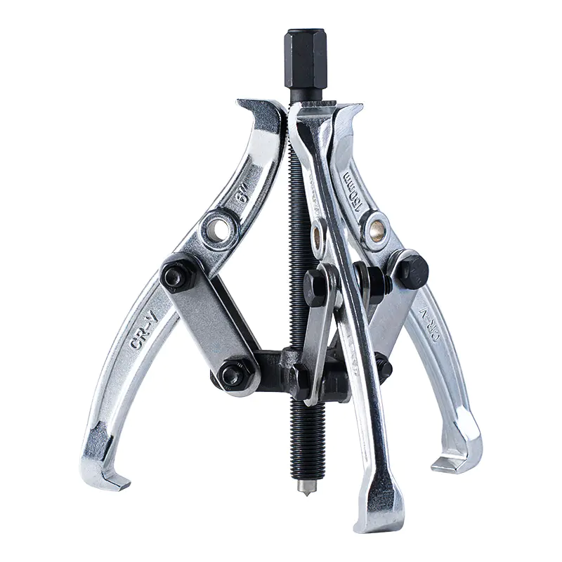
Model: SN0105
-
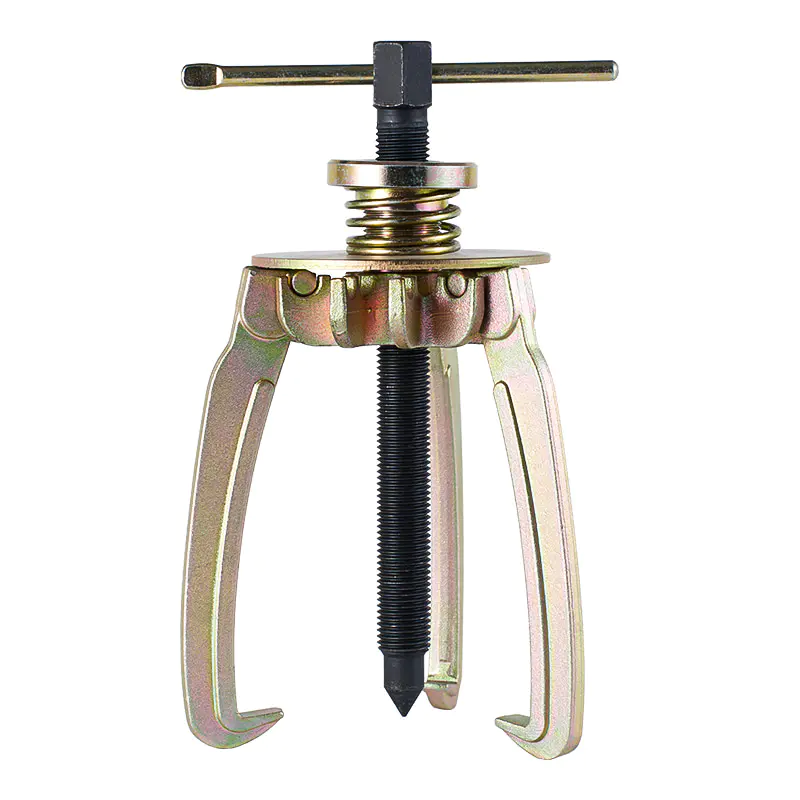
Model: SN0106
-
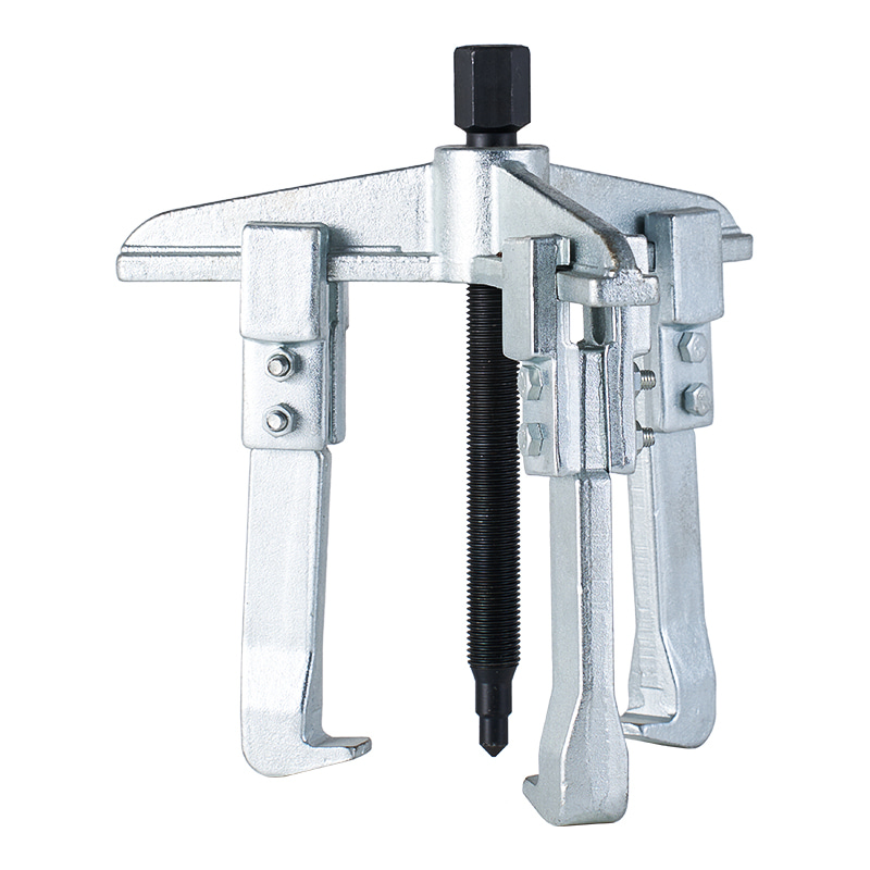
Model: SN0110
-
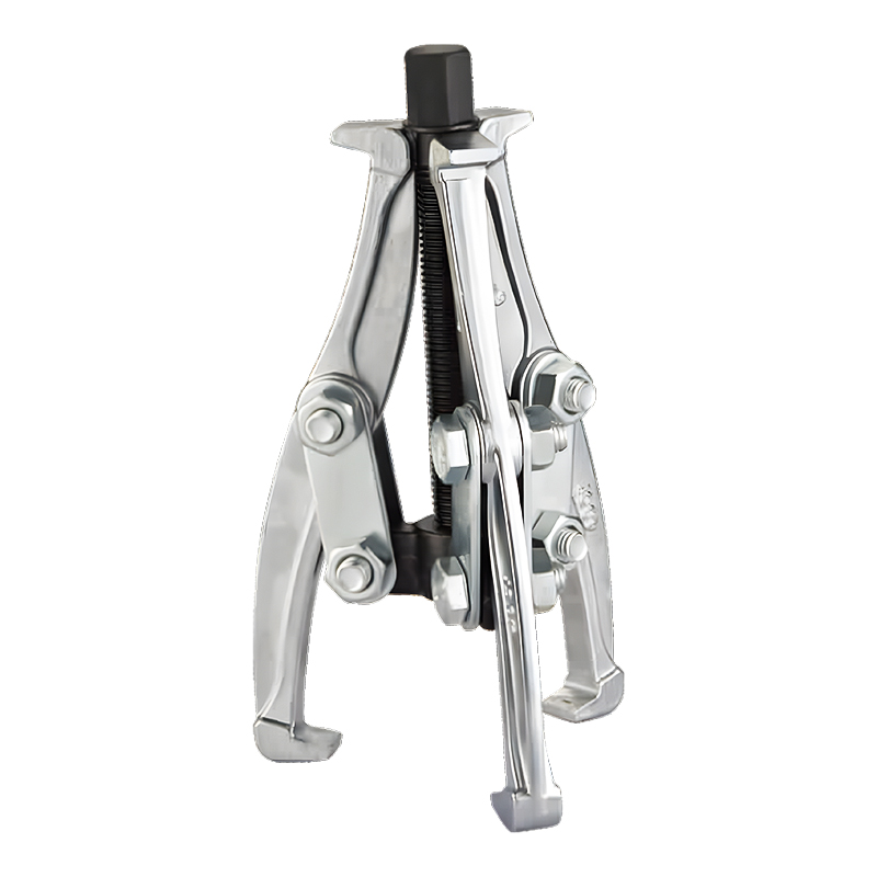
Model: SN0118
-
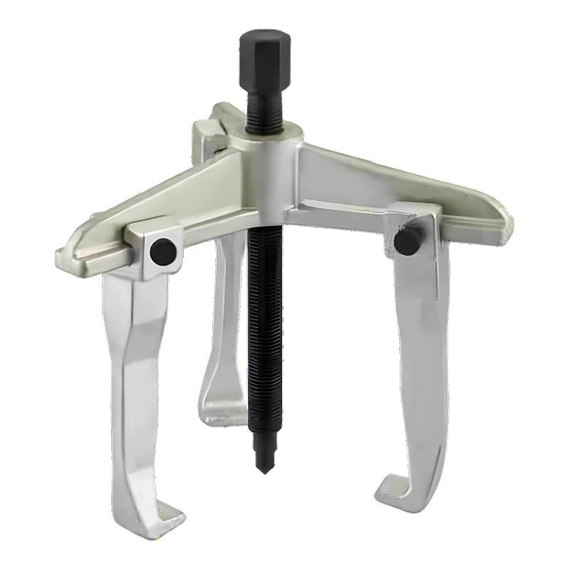
Model: SN0122
-
Model: SN0118-1
Submit feedback
What Is a Universal Bearing Puller and How Does It Work
2026-11-20
Bearings sit inside nearly every machine with rotating or moving parts. They cut friction, carry shafts, and keep components running smoothly. Getting them out is another story. Some are pressed tightly onto shafts, some sit deep in housings, and some hide behind other parts. Without the right tool, removal is awkward and can easily damage whatever is nearby.
A universal bearing puller is built for this job. It applies a controlled pulling force to take bearings off shafts, out of housings, or from other fitted positions. Its adjustable structure lets it handle different bearing arrangements, depending on the design and how much room you have.
It doesn't depend on hammering or twisting the bearing loose. A mechanical arrangement produces a steady pull instead, so the removal is more controlled and the surrounding parts take less unnecessary force.
You'll find these pullers in automotive repair, industrial maintenance, agricultural machinery servicing, and many other mechanical settings. Knowing how they're built, how they work, and where they fit helps technicians pick the right tool for each job.
What Is a Universal Bearing Puller ?
A bearing puller is a mechanical tool for separating bearings from shafts or other fitted components. Adjustable pulling parts let it adapt to different bearing sizes and installation positions.
"Universal" refers to its flexibility across removal tasks. It doesn't mean one puller can deal with every bearing or every mechanical structure. Compatibility still depends on the jaw arrangement, the pulling range, and the space around the bearing.
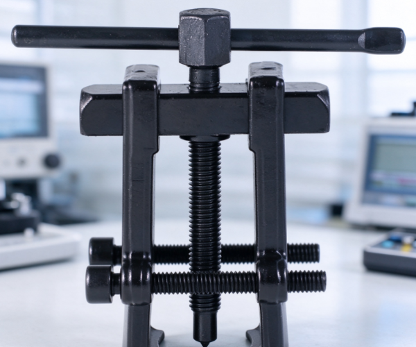
A typical puller has a central screw, pulling arms or jaws, a supporting frame, and some connecting parts. Together they grip the bearing and direct force the right way.
Once the tool is set up, the jaws catch the bearing or a suitable contact point behind it. The central screw rests against the shaft or another stable surface. Turning the screw makes the arms draw the bearing off its seat.
This helps when a bearing won't come off by hand. It also avoids some problems of direct hammering, which can send unwanted force into the shaft, the housing, or neighboring parts.
Designs vary. Some pullers have two jaws and others have three. Certain models add adjustable arms or interchangeable attachments for different working conditions.
Whatever the look, the purpose stays the same: a stable grip and controlled pulling force during removal.
How Does a Universal Bearing Puller Work?
The principle is simple mechanical force. A central screw and a set of pulling arms combine to separate the bearing from its seat.
First, the jaws go around the bearing or behind a suitable supporting edge. The central screw is then lined up with the shaft or another solid contact point.
As the operator turns the screw, it presses against the contact surface while the arms pull on the bearing. Two opposing actions result: the screw pushes against the shaft, and the jaws pull the bearing away from its mount.
Little by little, the bearing comes free of the shaft or housing.
The process runs through these stages:
- Positioning the tool
Place the pulling arms around the bearing. Their contact points should be stable and suit the bearing's structure.
- Aligning the central screw
Set the screw against the shaft or another solid surface. Good alignment keeps the force pointed where it should go.
- Applying pulling force
Turn the screw gradually. The arms pass the resulting force on to the bearing.
- Separating the bearing
As the force builds, the bearing starts to leave its seat. Keep going until it can be lifted away.
- Removing the tool
With the bearing free, back off the screw and take the puller out of the work area.
| Working Stage | Main Action | Purpose |
|---|---|---|
| Positioning | Place the jaws around the bearing | Establish a stable grip |
| Alignment | Position the central screw | Direct the pulling force |
| Force Application | Turn the central screw | Create controlled movement |
| Bearing Separation | Draw the bearing away from its mounting position | Remove the fitted bearing |
| Tool Removal | Release the pulling structure | Complete the operation |
Results depend on good contact and alignment. Jaws that aren't seated securely can slip. A misaligned screw can make the bearing move unevenly or strain the parts around it.
So take your time with positioning. It is a real part of the job.
What Are the Main Parts of a Universal Bearing Puller?
Designs differ, but most pullers share a similar basic structure. Each part has a role in holding the bearing and passing on the pulling force.
Knowing them helps you understand the tool and see what to check before use.
Central Screw
This is the main force-applying part. It sits in the middle of the puller and moves when the operator turns it. Its tip rests on the shaft or another stable surface.
The screw creates the movement that draws the bearing off its seat. Its threads let the operator build up force gradually, with no sudden impact.
Pulling Arms or Jaws
The jaws grip the bearing or a suitable edge behind it. They attach to the main body and carry the pulling force to the bearing.
Their shape and position decide how firmly the tool holds. Some jaws have narrow tips for tight spaces, while others are made for wider gripping areas.
Supporting Frame or Crossbar
The frame links the pulling arms and keeps them in place. It also gives structural support while the screw applies force.
A stable frame preserves the relationship between the jaws and the screw throughout the pull.
Connecting Components
Pins, bolts, and similar parts hold the sections together. They let the jaws move or adjust without the assembly coming apart.
They also affect how easily the tool can be set up for different bearing arrangements.
| Component | Main Function | Common Inspection Points |
|---|---|---|
| Central Screw | Applies mechanical force | Thread condition and surface wear |
| Pulling Arms | Grip and pull the bearing | Deformation and contact damage |
| Supporting Frame | Holds the tool structure together | Cracks and structural damage |
| Connecting Pins | Link movable components | Looseness and wear |
| Jaw Tips | Contact the bearing or supporting edge | Surface damage and slipping |
Some designs add more parts, such as adjustable arms, interchangeable jaws, or special attachments for particular removal tasks.
Those differences change how the tool fits into various mechanical assemblies.
What Are the Differences Between Two-Jaw and Three-Jaw Bearing Pullers?
The number and layout of the jaws matter when you choose a puller. Two-jaw and three-jaw designs are the usual options, and each has its own traits.
A two-jaw puller grips with two opposing arms. Its open structure helps when access is limited on one side or when nearby components leave no room for a third jaw.
The operator must place both jaws with care, though. Uneven contact can tilt the bearing as it comes off.
A three-jaw puller has three arms spaced around the bearing. This spreads the pulling force over several contact points and helps keep the bearing centered during removal.
It often suits arrangements with enough space around the bearing. In narrow areas, the extra jaw can make positioning harder.
| Comparison | Two-Jaw Puller | Three-Jaw Puller |
|---|---|---|
| Jaw Arrangement | Two opposing jaws | Three jaws around the bearing |
| Contact Points | Two | Three |
| Tool Structure | Relatively open | More surrounding contact |
| Working Space | May suit certain restricted positions | Requires room for jaw placement |
| Positioning | Requires balanced placement | Requires proper alignment of all jaws |
| Common Use | Selected bearing removal tasks | Bearing removal where multiple contact points are suitable |
Neither one fits every situation. The choice depends on where the bearing sits, what surrounds it, and which contact surfaces are available.
A bearing close to a wall or deep inside a tight assembly, for instance, can be hard to reach with three jaws. A two-jaw model may give you more room to maneuver there.
When there's plenty of space around the bearing, a three-jaw puller can give a more balanced grip.
Always check the actual design and compatibility of the tool before you start.
Where Are Universal Bearing Pullers Commonly Used?
These pullers turn up wherever bearings must come out during equipment maintenance. The adjustable structure suits many assemblies, though the right puller still depends on the application.
Automotive Maintenance
Vehicles have bearings in many systems. During repairs, technicians may need to remove them from wheel assemblies, transmission parts, alternators, and more.
A universal puller can free fitted bearings without direct impact. That matters when nearby components need to stay undamaged.
Different automotive assemblies call for different jaw arrangements. The tool has to suit the bearing position and the structure around it.
Industrial Machinery
Industrial equipment is full of bearings supporting rotating shafts and moving assemblies. They may come out during scheduled maintenance or when something goes wrong.
Pullers get used on motors, pumps, gearboxes, and other equipment. Being adjustable, they help maintenance teams cope with a range of removal tasks.
Agricultural Equipment
Farm machinery works amid dust, moisture, and other harsh conditions that wear on mechanical parts.
Bearings in tractors, harvesters, and similar machines may need inspection or replacement after long use. A suitable puller lets technicians take out fitted bearings during repairs.
Manufacturing and Processing Equipment
Production lines contain many rotating assemblies, and bearings keep them moving steadily.
A worn or damaged bearing may have to come out before the surrounding assembly can be serviced. Universal pullers earn their place in workshops that handle many kinds of machinery.
General Mechanical Repair
Repair shops see equipment from all sorts of industries. Rather than keeping a separate tool for each bearing arrangement, technicians can use adjustable pullers for compatible jobs.
Even so, the tool must match the bearing structure and installation position.
What Should You Consider When Choosing a Universal Bearing Puller?
Picking a puller takes more than a glance at its looks. It has to fit the bearing, the working environment, and the mechanical structure around the installation point.
These factors help narrow the choice.
Bearing Size and Structure
The bearing's outer shape and position determine where the jaws should go. The puller needs a suitable gripping range and contact structure.
A tool that is too big or too small may not hold the bearing securely. Identify the bearing type first, then check whether the puller can reach the intended contact points.
Available Working Space
Not every bearing sits in the open. Some are surrounded by housings, shafts, gears, or other components.
The room you have decides whether the arms can be positioned properly. A compact design may suit restricted areas, while a larger one works better on accessible assemblies.
Jaw Design
Jaw shape affects the grip. Some are meant for gripping behind the bearing, while others suit different contact arrangements.
The jaws should fit the removal position without harming nearby parts, and their contact surfaces should be in good condition.
Material and Structural Strength
A puller has to withstand the forces of removal. The central screw, arms, and frame should be built for the intended use.
Material quality and manufacturing consistency affect service life. Look for visible defects, damaged threads, and signs of deformation.
Ease of Adjustment
An adjustable design helps with different bearing arrangements. The adjustment mechanism should still stay secure while in use.
Loose connections or poorly fitted parts can make the pull unstable.
Application Requirements
A puller in an automotive shop faces different demands from one in an industrial maintenance facility. Base the choice on the equipment you service and how often you'll use the tool.
Weighing these points helps buyers find a tool that fits their real maintenance needs.
How Can You Use a Universal Bearing Puller Safely?
A puller makes removal more controlled, but careless use can still damage the tool or the equipment. Safe work comes down to correct positioning, the right tool, and attention to the condition of the assembly.
Before you begin, inspect the puller. The screw should turn freely, the jaws should be free of visible damage, and the connecting parts should be secure.
Examine the bearing and its surroundings too. Find a suitable gripping position and check that the shaft or another contact surface can support the screw.
When installing, make sure the jaws are properly seated. They should hold the bearing firmly, not rest on an unsuitable edge or a nearby component.
Keep the screw aligned with the shaft. An angled screw creates uneven force and may make the bearing move the wrong way.
Turn the screw gradually and watch how the bearing responds. Avoid sudden force or over-tightening. If the bearing doesn't move as expected, stop and check the jaw position, the alignment, and anything that might be restricting it.
Watch out for these common mistakes:
- Incorrect jaw placement: Poor contact may cause the tool to slip or damage the bearing.
- Misaligned central screw: Uneven force can disrupt removal and stress nearby parts.
- Using an incompatible puller: A tool that doesn't match the bearing may not grip securely.
- Ignoring tool damage: Worn threads or bent jaws can make the setup unstable.
- Applying excessive force: Forcing a stuck bearing may damage the shaft, housing, or puller.
Wear personal protective equipment during mechanical work. Follow the manufacturer's instructions and keep your hands away from loaded or moving parts.
If a bearing stays stuck, find out why before adding more force. Corrosion, deformation, or a poor gripping position may call for a different removal approach.
Why Is Regular Maintenance Important for Bearing Pullers?
A universal bearing puller is a reusable tool, and like any workshop equipment it wears with repeated use. Regular inspection catches problems before they affect how the tool performs.
Give the central screw special attention, since it applies the force directly. Damaged threads or a worn tip can spoil smooth movement and alignment.
Check the pulling arms as well. Bent arms, worn jaw tips, or surface cracks can weaken the grip on a bearing.
Pins and adjustment points can work loose after many uses. If they aren't kept in order, the jaws may shift unexpectedly during a pull.
A basic maintenance routine could cover the following:
| Maintenance Item | Inspection Focus | Suggested Action |
|---|---|---|
| Central Screw | Thread damage, dirt, and corrosion | Clean and maintain according to the manufacturer's instructions |
| Pulling Arms | Bending, cracks, and surface wear | Replace damaged components |
| Jaw Tips | Contact surface condition | Check for wear or deformation |
| Connecting Parts | Looseness and damage | Tighten or replace when necessary |
| Tool Body | Cracks and structural changes | Stop using damaged tools |
| Storage Condition | Moisture, dust, and contamination | Clean and store in a dry location |
Storage counts too. After use, wipe off dirt and grease and check whether anything was damaged during the job.
Keep the puller somewhere clean and dry to lower the risk of corrosion. Leave adjustable parts properly positioned so the tool is ready for the next task.

-

Fax: +86-576-82686606
-

Tel: +86-576-82686563
+86-576-82686832 -

E-mail: [email protected]
-

Add: Fengjiang Industrial Park, Luqiao Area,Taizhou City, Zhejiang Province, China
Copyright © 2025 Taizhou Xinming Technology Co., Ltd. All Rights Reserved.

Sale Hardware Tools Factory