

 русский
 Español
 عربى
عربى-
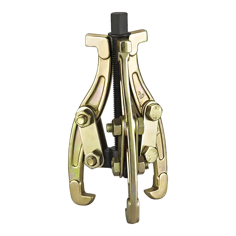
Model: SN0101
-
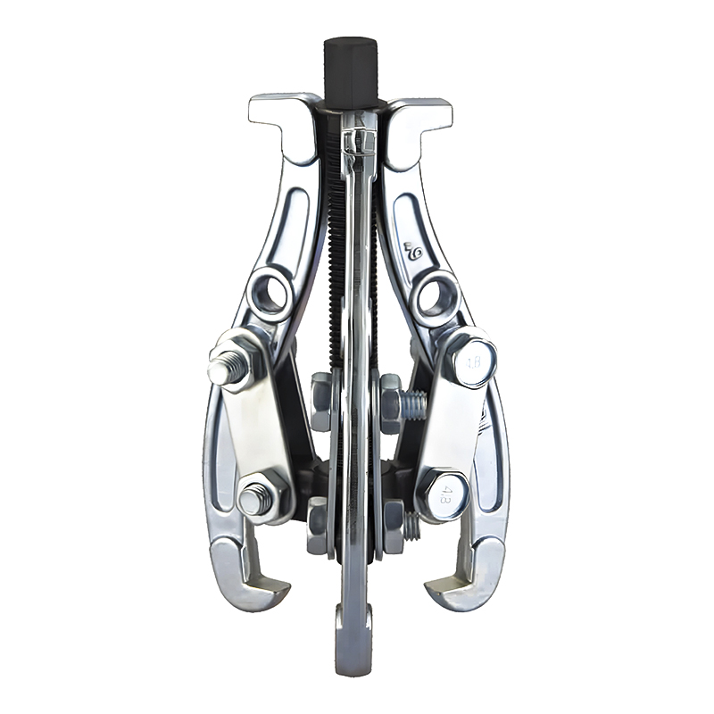
Model: SN0102-1
-
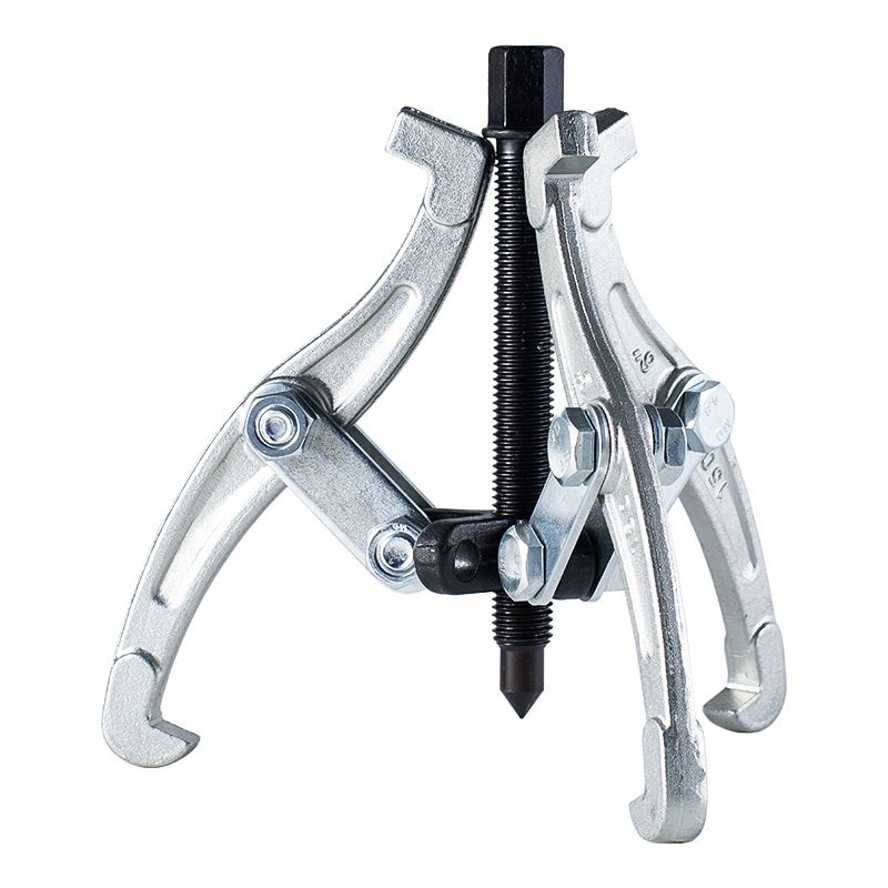
Model: SN0103
-
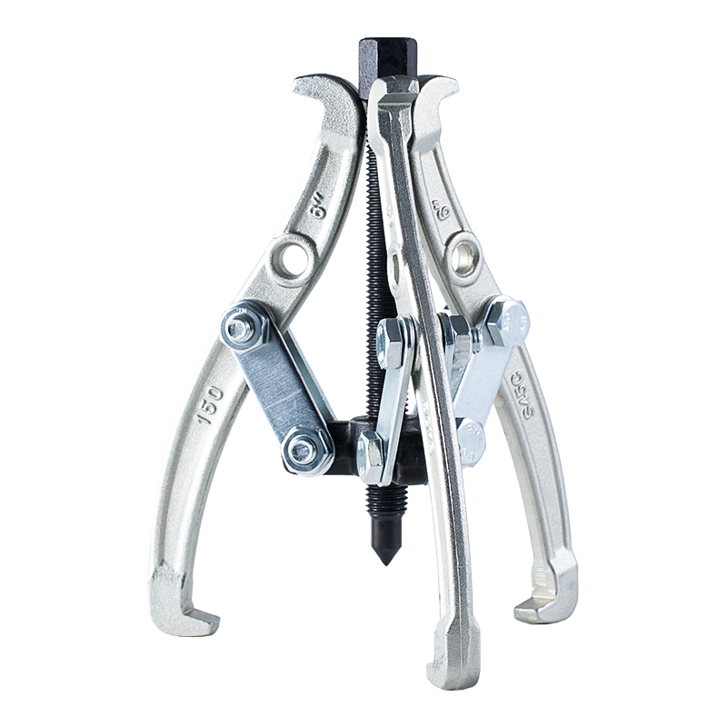
Model: SN0102 SN0107
-
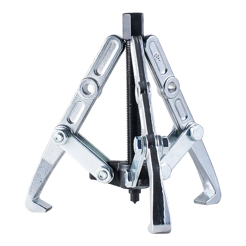
Model: SN0108 SN0109
-
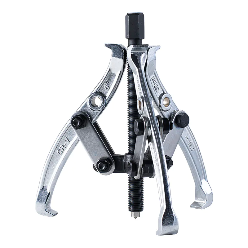
Model: SN0105
-
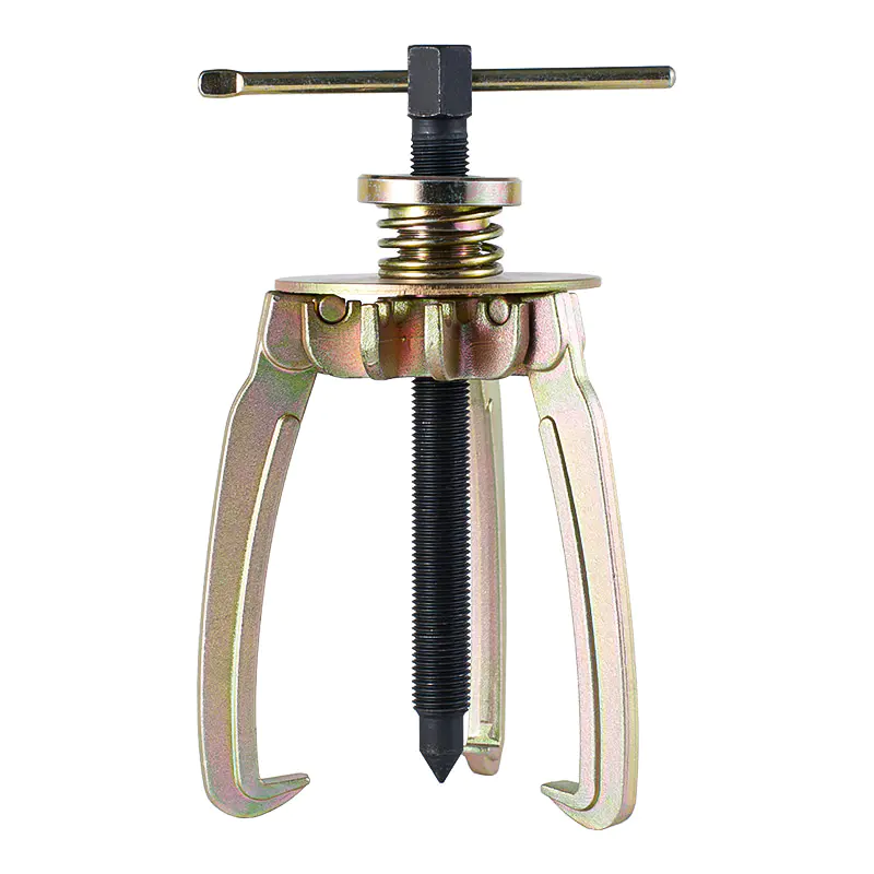
Model: SN0106
-
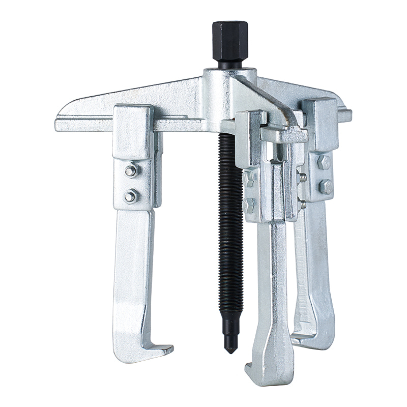
Model: SN0110
-
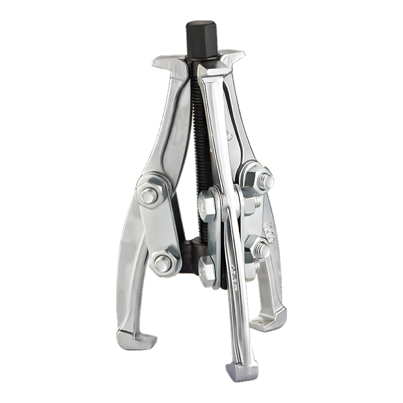
Model: SN0118
-
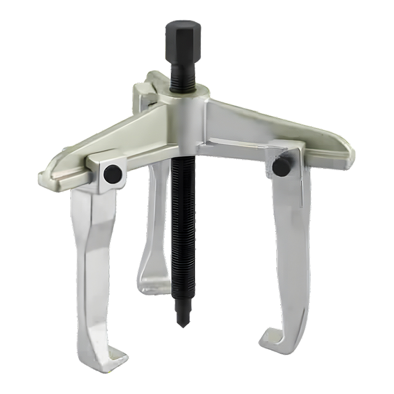
Model: SN0122
-
Model: SN0118-1
Submit feedback
How Does an Adjustable Gear Puller Work
2026-10-16
Mechanical parts are generally designed to stay firmly in place while equipment is running. Gears, bearings, pulleys, hubs, and similar components need a stable connection during normal operation, which is exactly the point. That same tight fit, though, turns into a real challenge the moment a part actually needs to come off for repair or maintenance work.
Trying to pry a tightly fitted component off by hand rarely gives anyone enough control over the process. Reaching for an unsuitable tool can put force in the wrong spot entirely and make the whole repair harder than it needs to be. A tool built specifically for controlled removal makes the job a lot more manageable.
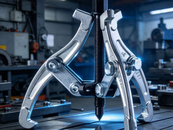
An adjustable gear puller is exactly that kind of tool. It uses a set of gripping arms along with a central forcing section to apply pulling force onto a component. Those arms adjust to fit different shapes and sizes of parts, which gives the tool a lot more flexibility across different maintenance jobs.
Understanding how an adjustable gear puller actually works matters for mechanics, maintenance teams, tool buyers, and manufacturers alike. The working principle isn't complicated at all, but each part of the tool carries a specific job in creating that controlled pulling action.
What Is an Adjustable Gear Puller ?
Gear puller is a mechanical removal tool built to help take fitted components off a shaft or mounting position. It typically includes several adjustable arms, a central screw or forcing section, and a body connecting all these pieces together.
The arms reach around whatever component needs removing. Their ends grip an appropriate edge or surface on that part. The central section then sits against the shaft or some other stable point. Once the forcing section gets turned, it creates movement between the tool's center and the gripping arms.
That combination is what produces the actual pulling action.
The tool isn't simply grabbing a component and yanking it loose. Its structure sets up a controlled relationship between the part being removed and the fixed point sitting behind it. As the central section moves, the gripping arms hold steady contact with the component while the pulling force builds up gradually rather than all at once.
The adjustable design matters here because mechanical components rarely share the same shape. A fixed tool might work fine for one specific job, while an adjustable design can flex to fit a much wider range of components.
| Part | Main Role |
|---|---|
| Adjustable arms | Grip the component being removed |
| Central forcing section | Creates the pulling action |
| Tool body | Connects and supports the main parts |
| Grip ends | Maintain contact with the component |
| Adjustment mechanism | Changes the position of the arms |
The exact structure may vary between tool designs, but the basic idea remains similar. The tool creates a controlled pulling force between the component and its supporting shaft or surface.
How Do the Arms Create the Pulling Action?
The arms are one of the most visible parts of an Adjustable Gear Puller. Their job is to hold the component securely while the central section produces the force needed for removal.
Before the tool is used, the arms are positioned around the outside of the component. The user adjusts their location so that the grip points make suitable contact with the part.
Once the arms are in place, the central forcing section is aligned with the shaft or another stable point. This creates a connection between three areas: the tool center, the component, and the supporting point.
When the central section is turned, it moves against the supporting point. The tool body transfers this movement toward the arms. Because the arms are holding the component, the component begins to move away from its original position.
This process can be viewed as a simple sequence:
1. The arms are placed around the component.
2. The arm positions are adjusted for a suitable grip.
3. The center of the tool is aligned with a stable point.
4. The central forcing section is turned.
5. The tool creates a pulling action.
6. The component gradually moves away from its fitted position.
The arms need to stay properly positioned throughout the process. A stable grip helps the pulling force remain directed toward the intended movement rather than shifting away from the component.
This is why the adjustment mechanism matters. It allows the user to position the arms according to the shape of the part instead of relying on one fixed arrangement.
Why Is Adjustability Important?
Mechanical repair work rarely involves components with identical shapes. A gear may have a different outer form from a pulley. A bearing may provide a different gripping surface from a hub. Even components serving similar purposes can have different structures.
An adjustable tool gives the user more freedom when positioning the arms.
The adjustment can help the tool fit around a wider range of components. It may allow the arms to move closer together or farther apart. The position can then be changed to create a more practical gripping arrangement.
This flexibility is useful in maintenance environments where different components may need to be removed during the same type of repair work.
| Repair Situation | Value of Adjustable Arms |
|---|---|
| Different component shapes | Helps create a suitable grip |
| Different component sizes | Allows arm positions to be changed |
| Limited working space | Gives more positioning options |
| Various maintenance tasks | Makes one tool useful across different jobs |
| Different gripping locations | Helps the user choose an appropriate contact area |
Adjustability does not mean that every puller is suitable for every component. The shape of the part, available gripping surface, tool design, and repair situation still need to be considered.
The purpose of the adjustment feature is to provide more practical positioning options. It gives the user greater control over how the tool connects with the component.
How Does the Central Screw Support the Removal Process?
The central screw, or forcing section, is really what creates the movement that makes the entire pulling action possible in the first place.
Once the arms are positioned around the component, the tool's center gets placed against a stable surface, usually tied back to the shaft the component is actually mounted on.
As the central section turns, it moves relative to the tool body. Contact between the center and that supporting surface generates force, and the surrounding structure carries that force through to the arms.
The end result is a gradual pulling movement, not a sudden jerk.
This approach differs a lot from simply hammering on a component or trying to wrench it loose with some makeshift tool. The central mechanism gives the user a way to build up force progressively over time. The component can start shifting without needing some sudden, forceful jolt to get it moving.
The central section needs to stay properly aligned the whole time it's in use. If the tool sits at an angle, the pulling action might not travel directly along the path it's supposed to follow. Keeping things properly positioned helps the tool stay stable and makes the whole removal process a lot easier to control from start to finish.
That's exactly why using an adjustable gear puller involves more than just cranking the center screw. The arms, the body, the center, and the component all need to work together as one coordinated system.
Where Are Adjustable Gear Pullers Commonly Used?
Gear Pullers are commonly associated with mechanical repair and maintenance. Their purpose is particularly useful when a component has a tight fit and needs to be removed without relying on uncontrolled force.
Automotive maintenance is one area where this type of tool can be useful. Vehicles contain many rotating and fitted components. During repair work, mechanics may need to remove parts from shafts before inspecting or replacing them.
Industrial maintenance is another common application. Machines used in production and equipment systems may contain gears, pulleys, bearings, and hubs that require periodic servicing.
The tool may also be useful in general mechanical workshops where different types of equipment are repaired.
Common application areas include:
- Automotive repair
- Industrial machinery maintenance
- Mechanical workshops
- Equipment servicing
- Rotating component replacement
- General repair operations
- Bearing and gear removal work
The exact application depends on the component and the puller design. A tool should be selected according to the part that needs to be removed rather than simply according to the general category of the repair.
What Parts Can an Adjustable Gear Puller Help Remove?
The name Adjustable Gear Puller may suggest that it is intended only for gears. In practice, similar pulling principles can apply to several types of fitted mechanical components.
Gears are a common application because they are often mounted on shafts and may need to be removed during equipment maintenance. The puller arms can grip an appropriate part of the gear while the central section pushes against the shaft.
Bearings are another common application. When a bearing is fitted tightly, removing it by hand may not be practical. A suitable pulling tool can create a controlled force that helps separate the bearing from its mounting position.
Pulleys and hubs may present similar challenges. These parts can be firmly seated on shafts and may require a tool that reaches around the component while pushing against a stable center point.
The following table shows some common examples:
| Component | Why a Puller May Be Used |
|---|---|
| Gear | Helps separate the gear from a shaft |
| Bearing | Supports controlled removal from a fitted position |
| Pulley | Provides a way to pull the pulley away from its shaft |
| Hub | Helps remove a firmly fitted hub |
| Similar rotating parts | Offers a controlled method of separation |
Not every component can be removed with the same puller arrangement. Some parts may have limited gripping space or a shape that does not allow the arms to sit correctly. The available contact area needs to be considered before use.
How Should an Adjustable Gear Puller Be Positioned?
Positioning has a direct effect on how the tool performs. Even a suitable puller may not work properly if its arms are placed unevenly or the center is not aligned with the supporting point.
The arms should normally contact the component in a balanced arrangement. They need to hold a stable area rather than resting on a weak or unsuitable edge.
The central section should then be aligned with the shaft or another firm surface behind the component. This creates a direct path for the pulling force.
A simple preparation process can help:
1. Inspect the component.
Identify how it is fitted and where a safe gripping surface is available.
2. Choose the appropriate puller position.
Place the arms around the component without forcing them into an unsuitable location.
3. Adjust the arms.
Move the arms until they maintain a stable connection with the component.
4. Align the center.
Make sure the central forcing section meets the supporting point in a suitable position.
5. Check the grip.
Confirm that the arms remain seated before applying force.
6. Apply the pulling action gradually.
Turn the central section in a controlled manner and observe the movement of the component.
If the component does not move as expected, increasing force without checking the setup may not solve the problem. The tool position, gripping surface, or removal method may need to be reconsidered.
Good positioning is therefore part of the working principle itself. The puller depends on a stable relationship between the arms, the component, and the central support point.
What Should Buyers Consider When Choosing an Adjustable Gear Puller?
Choosing an Adjustable Gear Puller involves more than looking at the word "adjustable." Buyers need to consider how the tool will be used and what types of components it will encounter.
The arm arrangement is one consideration. Different designs may provide different ways to reach around a component. Buyers should consider whether the arms can be positioned where they are needed during actual repair work.
The gripping ends are another area to examine. The contact point should match the shape of the components being removed. A tool may be adjustable, but adjustment is only useful when the arms can create a stable grip.
The central forcing mechanism should be considered as well. Its position needs to work with the shaft or supporting surface involved in the repair.
Tool handling can matter in regular maintenance work. A design that is easy to position and adjust may help users prepare the tool more efficiently.
Buyers can use several practical questions when comparing products:
- What types of components will the tool be used to remove?
- Can the arms be adjusted to fit those components?
- Do the gripping ends provide a suitable contact area?
- Is the central section easy to position?
- Does the tool fit the available working space?
- Is the construction appropriate for the intended repair environment?
- Does the manufacturer provide clear product information?
- Can the supplier support different tool requirements?
For businesses purchasing tools for maintenance teams, these questions can help connect the product design with actual repair tasks.
An Adjustable Gear Puller works through a straightforward mechanical relationship. The adjustable arms grip the component, the central section provides the pulling movement, and the tool body transfers that force between the two. When the parts are positioned correctly, the component can gradually separate from its shaft or mounting location.
That basic structure gives the tool a useful role in automotive repair, industrial maintenance, equipment servicing, and other mechanical work where fitted components need to be removed in a controlled manner.

-

Fax: +86-576-82686606
-

Tel: +86-576-82686563
+86-576-82686832 -

E-mail: [email protected]
-

Add: Fengjiang Industrial Park, Luqiao Area,Taizhou City, Zhejiang Province, China
Copyright © 2025 Taizhou Xinming Technology Co., Ltd. All Rights Reserved.

Sale Hardware Tools Factory